
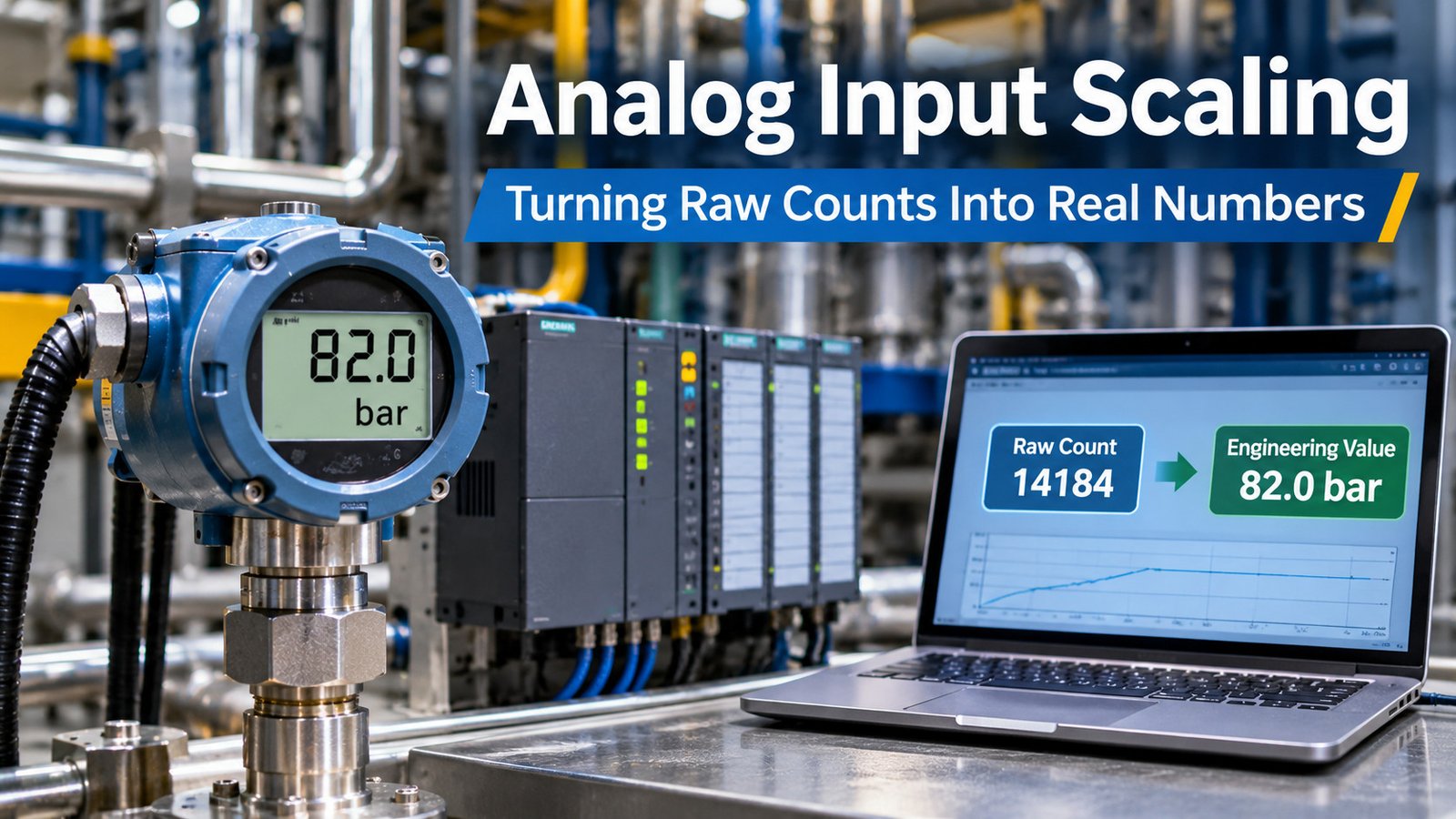
The gauge on the panel reads 82 bar. The PLC says 14184. Somebody has to make those two numbers agree, and that job is analog input scaling. I have watched good electricians freeze at this step because the manual throws integers at them and never says what the integers mean.
Here is the short version. Every analog module turns a voltage or a current into a whole number. Your job is to map that number onto the range printed on the transmitter tag.
What analog input scaling actually does
An analog input card has one job. It measures a signal, converts it, and hands the CPU a raw integer. That integer is not pressure. It is a count, and the count means nothing until you tell the PLC what the endpoints are.
Think of a ruler with no markings. The card says the measurement landed 4,312 ticks from the left edge. Useless until you know how many ticks span the full length and what the ruler measures.
The endpoints come from two places. Your module fixes the raw count range. The transmitter tag fixes the engineering range. Analog input scaling is nothing more than joining those two scales with a straight line.
Three things must be true first.
- ☐ Raw minimum and maximum come from the module data sheet, never from memory.
- ☐ Engineering minimum and maximum come from the instrument tag, never from the process display.
- ☐ Both pairs describe the same physical span.
If you cannot state both spans in one breath, you are not ready to write the block.
The formula and the three numbers you need
The math is a two-point line. You need three numbers: the raw span, the engineering span, and the offset.
Engineering value = ((raw – raw_min) x (EU_max – EU_min) / (raw_max – raw_min)) + EU_min
For the common case where the raw range starts at zero, it collapses to something you can do in your head:
Engineering value = raw x (EU_max – EU_min) / raw_max + EU_min
That is the version used on a Siemens 4-20 mA channel, where the raw count runs 0 to 27648.
Table 1: The numbers you need before writing any scaling block
| Number | Where it comes from | Example |
|---|---|---|
| raw_min | module data sheet | 0 |
| raw_max | module data sheet | 27648 |
| EU_min | instrument tag | 0 bar |
| EU_max | instrument tag | 160 bar |
Worked example: 160 bar over 4-20 mA
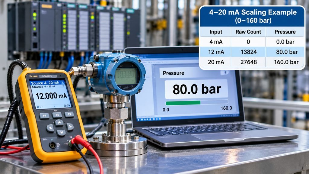
Now a worked example. Siemens 4-20 mA channel, transmitter ranged 0 to 160 bar, raw maximum 27648.
raw     0  ->       0 x 160 / 27648  =   0.0 bar
raw 13824  ->   13824 x 160 / 27648  =  80.0 bar
raw 27648  ->   27648 x 160 / 27648  = 160.0 bar
Half the counts, half the range. That gives you a free field check. Push 12 mA from a calibrator and the HMI must read 80 bar. If it reads 78 or 83, the scaling or the transmitter is off, and you have two suspects instead of none.
Image suggestion, immediately after that ladder: a bench photo of a loop calibrator clipped to a pressure transmitter with the HMI screen in frame. Alt text: “analog input scaling checked at three points with a loop calibrator”.
Field note: push 4, 12 and 20 mA and write down all three readings. Three numbers tell you whether you have an offset error, a span error, or a bad instrument.
Bipolar ranges and the zero offset
Bipolar ranges use the same line. Take a Siemens +/-10 V channel mapped to -50 to +150 degC. The raw span is 55296 counts and the engineering span is 200 degrees.
Table 2: Bipolar +/-10 V channel mapped to -50 to +150 degC
| Input | Raw count | Engineering value |
|---|---|---|
| -10 V | -27648 | -50 degC |
| 0 V | 0 | +50 degC |
| +10 V | 27648 | +150 degC |
Zero volts lands at +50 degC, not 0 degC, because the engineering range is not centered on zero. Get that wrong and every reading is out by 50 degrees. I have seen it on a furnace zone, and the operator spent a shift chasing an overheating problem that did not exist.
Analog input scaling on a Siemens S7-1200 or S7-1500
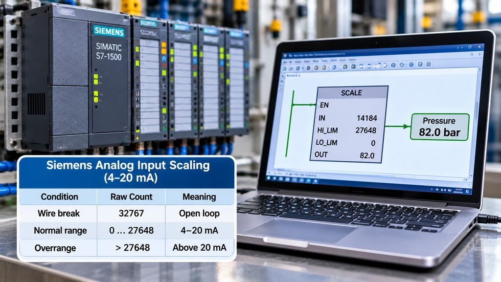
Siemens makes this easy once you accept their number. On S7-1200 and S7-1500 analog signal modules, current inputs report 0 to 27648 for the rated range. That covers 0-20 mA and 4-20 mA. Voltage inputs report -27648 to 27648, covering +/-10 V, +/-5 V and +/-2.5 V.
Anything outside those numbers is not process data. It is the module telling you something is wrong.
Table 3: Siemens raw counts for a 4-20 mA channel
| Condition | Raw count | Meaning |
|---|---|---|
| Wire break | 32767 | open loop |
| Overrange | above 27648 | above 20 mA |
| Rated maximum | 27648 | 20 mA |
| Mid range | 13824 | 12 mA |
| Rated minimum | 0 | 4 mA |
| Underrange | -1 to -691 | 3.9994 mA to 3.6 mA |
The voltage side behaves the same with different endpoints. Siemens documents 27648 as exactly +10 V and -27648 as exactly -10 V on the +/-10 V range. The value 32767 is overflow above +11.851 V, and -32768 is underflow.
In STEP 7 you do this in two steps. NORM_X normalizes the raw integer into a REAL between 0.0 and 1.0. SCALE_X stretches that onto your engineering limits.
Quick answer: NORM_X then SCALE_X. Set the NORM_X limits to 0 and 27648 for a 4-20 mA channel, then scale to your bar or degC limits.
The trap is the NORM_X limits. Leave them at the default and your zero point drifts the moment the loop drops under 4 mA.
Second trap: data type. NORM_X wants an integer and produces a REAL. Feed it a REAL that got divided upstream and the block returns nonsense.
Analog input scaling on a Mitsubishi FX5U
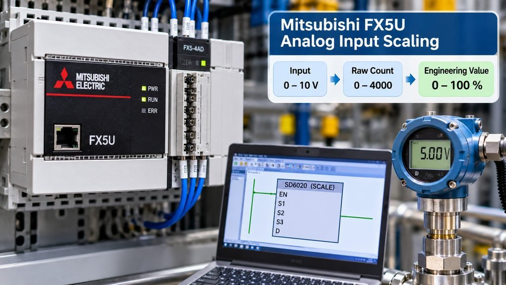
The FX5U is a different animal because the analog inputs sit in the CPU. Two channels, voltage only. 0-10 V DC, input resistance 115.7 kohm, unsigned 12-bit conversion, digital output 0 to 4000 counts. Resolution is 2.5 mV per count.
Accuracy is within +/-0.5%, stated as +/-20 digit, at 25 +/-5 degC. Fine for level, position and most temperature work through a transmitter.
Data lands in special registers: SD6020 for channel 1, SD6060 for channel 2. No configuration block. You read the register and scale it.
Table 4: FX5U built-in channel, 0-4000 counts to 0-100%
| Raw count | Calculation | Percent |
|---|---|---|
| 0 | 0 x 100 / 4000 | 0.000% |
| 1 | 1 x 100 / 4000 | 0.025% |
| 2000 | 2000 x 100 / 4000 | 50.000% |
| 4000 | 4000 x 100 / 4000 | 100.000% |
One count is 0.025%. On a 0-160 bar scale one count is 0.04 bar, and if you need better than that you need a different module, not a better formula.
Here is what catches people. The built-in channels are voltage inputs. A 4-20 mA transmitter cannot land there directly. You need a 250 ohm resistor to convert current to voltage, or an expansion module with current inputs. Check the data sheet for the exact count range, because expansion modules do not all share the 0-4000 span.
Warning: do not assume the FX5U built-in range matches an expansion module. The count span changes and your scaling block silently inherits the error.
For the math, a plain multiply is enough: engineering span divided by 4000. No normalize step, which makes the FX5U the easiest of the three.
Analog input scaling on an Allen-Bradley Logix controller
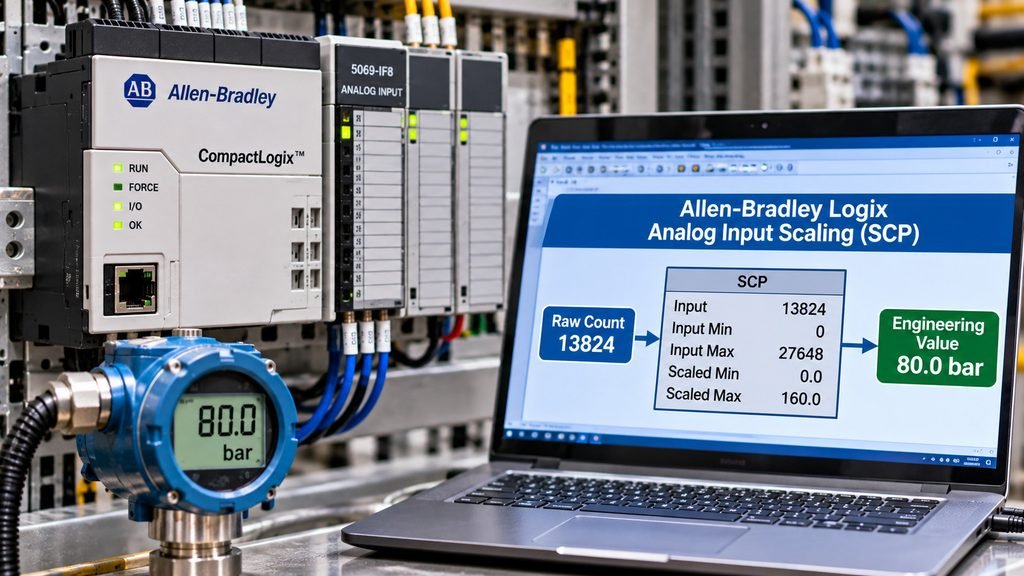
Logix cares about the two-point line, not the brand of the card. Give it an input minimum, input maximum, output minimum and output maximum, and it interpolates.
Most projects use an SCP block, Scale with Parameters: that is the four-parameter linear scale. The SCL instruction does the same linear math if you prefer to write it out.
Table 5: SCP parameters for a 4-20 mA channel ranged 0-160 bar
| Parameter | Value | Source |
|---|---|---|
| Input minimum | 0 | module data sheet |
| Input maximum | 27648 | module data sheet |
| Output minimum | 0.0 | instrument tag |
| Output maximum | 160.0 | instrument tag |
The exact block name depends on your project template. Some ship SCP as an add-on instruction, some use another name, some sites ban add-ons. Check the instruction set for your controller.
If your card reports 0 to 32767 instead of 0 to 27648, put 32767 in the input maximum. Do not copy a number from another project because the tag names looked similar. That is the most common cause of a reading that is out by a few percent and nobody can explain.
Some cards already hand you engineering units, and a second scale on top gives a reading off by a factor. Check the raw value in the tag monitor first.
What goes wrong (zero drift, wire break, overflow)
Three faults cover most of the bad readings I get called out to.
Zero drift is the quiet one. The transmitter reads 0.3 bar on a dead process, so every reading is 0.3 bar high. No formula fixes that. It is a zero trim, a grounding problem, or a 4-20 mA input where the live zero was never accounted for.
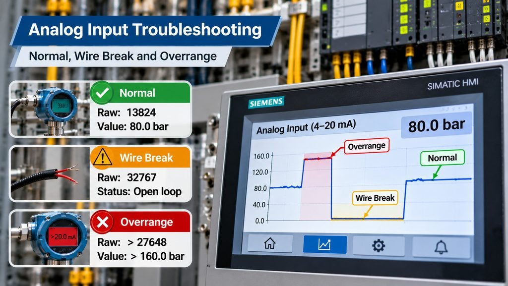
Wire break is the loud one. On Siemens analog boards where wire-break diagnostics apply, an open loop returns 32767 in 16#7FFF. The S7-1200 G2 analog board also returns 32767 below about 1.185 mA. Your block converts that into a number far above the engineering maximum and the HMI shows a pressure that does not exist.
Overflow is the confusing one. A count above 27648 on a current input means the signal exceeded 20 mA. Real overrange, a short, or a wiring error. Either way the number on screen is not trustworthy.
Siemens 4-20 mA channel scaled 0-160 bar
raw 27648  ->  160.0 bar   rated maximum, trust it
raw 30000  ->  173.6 bar   overrange, do not trust it
raw 32767  ->  wire break or under 1.185 mA, flag the fault
raw -691   ->    3.6 mA    underrange, check the loop
Caution: always add a range check after the scaling block. If the raw count sits outside the rated span, force a fault state instead of showing a number. A false 173 bar is worse than a blank screen.
Scale first, then validate. Never let a count outside the rated span reach the operator as a process value.
Checklist before you trust the number
Run this on every loop before you sign the sheet. It takes ten minutes and it saves callbacks.
- Read the module data sheet and write down the raw minimum, raw maximum and the overrange value.
- Read the instrument tag and write down the engineering minimum and maximum with units.
- Confirm the transmitter output type matches the card: 4-20 mA, 0-20 mA, 0-10 V or +/-10 V.
- Write the scaling block with explicit limits, no defaults left in place.
- Inject 4 mA, 12 mA and 20 mA and record the HMI reading at each point.
- Confirm 4 mA lands on the engineering minimum, 12 mA on the midpoint, 20 mA on the maximum.
- Disconnect one leg and confirm the display goes to a fault state, not a high number.
- Write both spans in the logic comment so the next person does not have to guess.
- ☐ Raw span recorded from the data sheet
- ☐ Engineering span recorded from the tag, with units
- ☐ Three-point calibration done and written down
- ☐ Wire break tested and handled
- ☐ Comment in the logic states both spans
If step 5 gives three readings off by the same amount, you have an offset problem. Three readings off by a growing amount mean a span problem. If only one of the three is off, the loop or the calibrator is suspect, not the code.
Analog input scaling is a straight line between two scales. The work is getting the four numbers right and refusing to trust a count outside the rated range. Do that and the number on the HMI matches the gauge on the panel.
About TZ Tech
TZ Tech supplies industrial automation, electrical, instrumentation and telecommunications components, including rare and discontinued parts other suppliers can’t source. We buy ready-to-ship distributor stock, so prices stay competitive and lead times stay short.
You get the part you ordered, at the price and lead time we quoted. Legacy and discontinued items come with an honest, accurate report on their real condition, so there are no surprises when the box arrives.
Send your inquiry and you hear back within 6 hours. In-stock items ship without delay.
Every component is screened and inspected before it leaves us. Brand-new parts carry a full 1-year warranty.
If a part isn’t right, we make it right, and we stay reachable after the sale.
Have a project or a part you need? Send us the details and we’ll get back to you fast.
Contact us →