

Thirty-one years. That is how long I have been standing in front of panels with a screwdriver in one hand and a printout in the other. And in all that time, no single topic has burned more weekend hours, more overtime, and more young technicians than the sinking versus sourcing argument.
Here is the thing. The physics is simple. It is genuinely, honestly simple. The problem is the language. Vendors, catalogs, distributors and the guy on the phone at the supply house all use the same two words to mean different things, and nobody warns you.
So let me be blunt up front. If you take one idea away from this, take the current direction rule, because it is the only thing that never lies to you. Labels lie. Datasheets get translated badly. Sales guys guess. Current does not guess.
I am going to show you both input types, walk you through a live panel test you can run in five minutes, and then hand you a table for outputs, because outputs are a whole separate set of decisions and mixing them up is how you let the smoke out.
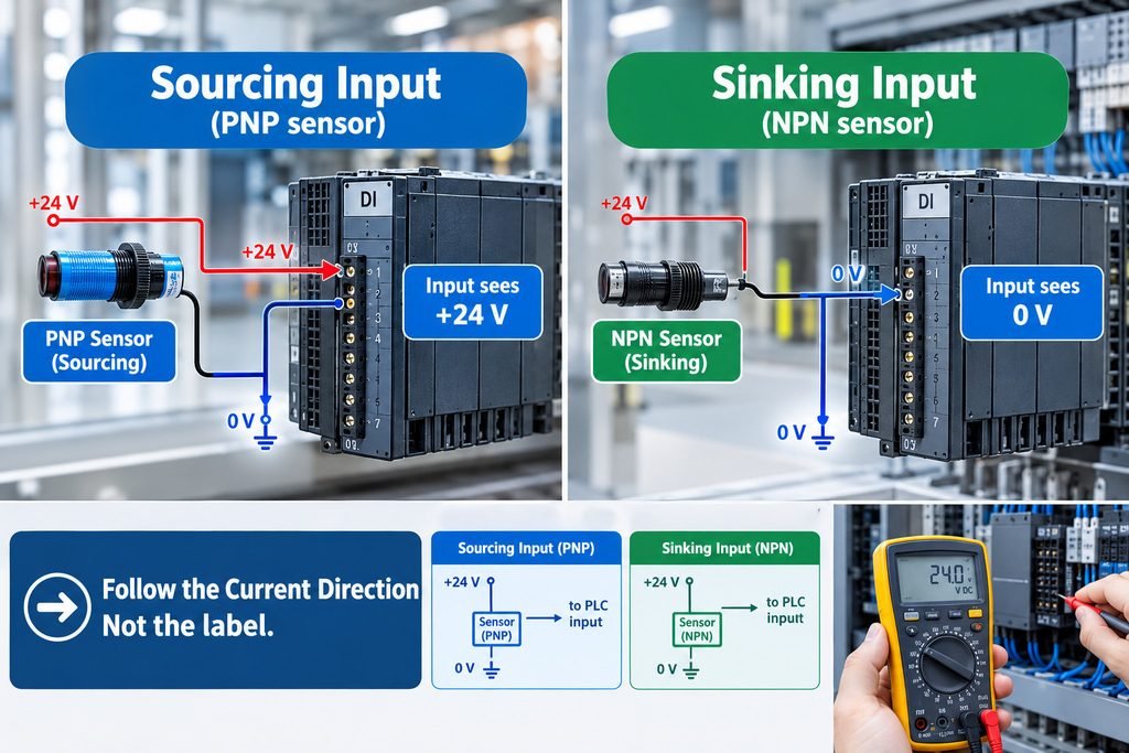
Quick answer: Sourcing input means the sensor pushes +24 V DC onto the input terminal. Sinking input means the sensor pulls the input terminal down to 0 V. Follow the current, not the label.
Two words that cost people a weekend
Let me tell you about a job. Small packaging line, retrofit, one cabinet, maybe forty input points. Good tech, young, careful. Ordered the modules from one distributor and the sensors from another because the sensor lead time was shorter.
Friday afternoon the line ran in manual but every single sensor read dead in the PLC. Forty points. He checked wiring for six hours. He swapped two sensors. He called me at eight in the evening, and I could hear the frustration in his voice.
The modules were sourcing input cards. The sensors were NPN three-wire units. Those two things cannot work together, not with any amount of wiring gymnastics. The sensors were fine. The cards were fine. The combination was dead on arrival.
That is the whole trap. Some vendors name the module after what the module does to the input circuit. Others name it after what the sensor must do. Same words. Opposite meanings.
Here is the map.
Table 1: The two naming conventions and what they actually mean
| What the vendor says | What they usually mean | Sensor family required | Current at the input terminal |
|---|---|---|---|
| “Sourcing input” | The module supplies the wetting voltage to the field device | NPN, sinking, low-side switch | Flows from module supply, through sensor, to 0 V |
| “Sinking input” | The field device supplies the voltage to the module | PNP, sourcing, high-side switch | Flows from sensor, through input circuit, to module common |
| “Positive logic” | Usually the same as sourcing input | Verify with the drawing | Check the drawing |
| “Negative logic” | Usually the same as sinking input | Verify with the drawing | Check the drawing |
Read that table twice, because half the confusion in this trade lives in those four rows.
Here is the warning that saves you money. The same physical module can be sold as one thing by one brand and the other thing by the next brand. There is no standards body policing this. There is no fine for mislabeling. So you read the drawing. Every time. Even when you are sure. Especially when you are sure.
Never buy sensors and input modules from different suppliers without confirming the input type in writing. The return shipping alone will cost more than the phone call. If you need to look up how a card is grouped before the order goes out, the control and monitoring category is the fastest place to check module families side by side.
The other half of the mess is the wording itself. Think about it physically. If I say a device is “sinking,” I could mean it sinks current in from the load. Or I could mean the module presents a sinking load. Both are grammatically fine. Both describe real circuits. Only one is the one you own.
So stop arguing with the label. Start asking where the electrons go.
Before we go further, if you are still assembling the cabinet itself, the electrical components catalog is where I would start on the field wiring side. Good terminations beat good theories every time.
Sourcing inputs: the sensor brings the voltage
A sourcing input card wants the field device to hand it voltage.
The sensor, a PNP three-wire unit, gets permanent power from the cabinet supply. Brown to +24 V DC, blue to 0 V. The black output wire is the switched line. When the sensor sees its target, it connects that black wire internally to the brown wire, and roughly 24 V DC appears on it.
You land the black wire on the input terminal. Internally the module has an input circuit that runs from that terminal, through an optocoupler or a resistor network, and back out to the module common. That common is tied to 0 V.
So the current path is: +24 V supply, into the sensor, out the black wire, into the input terminal, through the input circuit, out the module common, back to 0 V. A complete loop. The input circuit sees a high level and reports that input as ON.
Picture the drawing. A screw terminal labeled IN0. A wire with a ferruled end, probably 0.75 mm, going out to a sensor mounted on a bracket near the conveyor. An arrow on the drawing showing current flowing away from the sensor, into the card.
This is standard in European and Asian panel practice. The vast majority of European machine builders wire PNP. If you are working on a German or Italian or Japanese machine, assume PNP sourcing until the meter tells you otherwise.
Table 2: Sourcing input, signal by signal
| Sensor state | Voltage on black wire | Input terminal to module common | PLC reads | Current flowing |
|---|---|---|---|---|
| Target absent | Floating, pulled low internally | Near 0 V | OFF | None to speak of |
| Target present | Roughly +24 V DC | Roughly +24 V DC | ON | Yes, a few mA |
| Wire broken | Floating | Near 0 V | OFF | None |
Note the third row. A broken wire and a missing target look identical to a sourcing input. That is the reason a broken signal wire can sit undetected for months and only show up when the machine behaves strangely at three in the morning. Keep that in your head when you are troubleshooting an intermittent fault.
Rule of thumb: PNP sensor, sourcing input, voltage appears on the terminal when the target is present. If you see 0 V with the target there, the problem is the sensor or the wire, not the card.
One more practical detail. Most 3-wire sensors follow brown to +24 V, blue to 0 V, black as the switched output. That is the convention. It is not a law. I have opened sensors with blue and brown reversed, and I have opened sensors where the third wire was white. Check the sensor label. Ten seconds of reading beats ten hours of guessing.
Sinking inputs: the sensor pulls the line to zero
A sinking input is the mirror image, and mirror images are what break brains.
Here the module supplies the voltage. Internally the input terminal is pulled up to the module’s positive supply through a resistor or a current source. That is the wetting voltage, and it is there all the time, waiting.
The sensor is NPN. Brown to +24 V, blue to 0 V, black to the input terminal. When the sensor sees its target, it connects the black wire internally to the blue wire, meaning it connects the input terminal to 0 V.
Now the loop is: module positive supply, through the input circuit and out the input terminal, along the black wire, into the sensor, out the blue wire, to 0 V, and back to the supply return. The input circuit detects a low level at its terminal and reports that input as ON.
The current still flows. It always flows. It just flows the other way relative to the terminal.
Table 3: Sinking input, signal by signal
| Sensor state | Voltage on black wire | Input terminal to module common | PLC reads | Current flowing |
|---|---|---|---|---|
| Target absent | Pulled up by module | Roughly +24 V DC | OFF | None to speak of |
| Target present | Pulled to 0 V by sensor | Near 0 V | ON | Yes, a few mA |
| Wire broken | Pulled up by module | Roughly +24 V DC | OFF | None |
Now. Why does an NPN sensor on a sourcing-only module read nothing?
Because a sourcing input card does not have that internal pull-up on the terminal. It expects to be fed voltage. Land an NPN sensor on it and the most the card ever sees is 0 V, because the only thing the sensor can do is short the terminal to ground. There is no voltage source on that terminal to begin with. The input sits there, dark, forever.
Flip it. A PNP sensor on a sinking-only module. The card already holds the terminal at roughly +24 V through its pull-up. The sensor pushes +24 V onto the same node. Nothing changes. The card sees high when the target is there and high when it is not, because the pull-up is doing all the work. The input is stuck ON, or stuck in whatever state the leakage puts it in. Either way, it is not reading your sensor.
That is the failure. No explosion, no blown fuse, no fault code. Just a dead input or a stuck input. Which is why this costs a weekend instead of a fuse.
Bottom line: An NPN sensor on a sourcing card reads nothing. A PNP sensor on a sinking card reads stuck or wrong. Neither is a wiring mistake you can fix with a jumper.
Here is the ASCII version of both circuits, because a picture on a napkin is worth a page of prose.
SOURCING INPUT (PNP sensor brings the voltage)  +24 V ---- [ brown ]
               |
            [ sensor ] -- sees target --> closes to brown
               |
      black -->| IN0  (module input terminal)
               |
        [ input circuit inside module ]
               |
  module common (0 V) ---------------> back to 0 V rail
  Current: +24 V -> sensor -> IN0 -> input circuit -> common -> 0 V
  Target present  => IN0 sits near +24 V => input reads HIGH
SINKING INPUT (NPN sensor pulls the line to zero)
  +24 V ------------------------------------+
                                            |
                              [ internal pull-up ]
                                            |
      black -->| IN0  (module input terminal)
               |
            [ sensor ] -- sees target --> closes to blue
               |
            [ blue ] ---- 0 V rail
  Current: +24 V -> internal pull-up -> IN0 -> sensor -> 0 V
  Target present  => IN0 sits near 0 V => input reads LOW (which is ON)
Same current. Same physics. Opposite direction at the terminal. That is the sentence to remember.
If you are sizing the supply that feeds all of this, the power supplies section is worth a look, because input leakage current and sensor burden add up faster than people expect on a big rack.
Read the module drawing before you buy the sensor
Here is my actual work order for a retrofit. Not the catalog order. The one that happens first.
Look at the module. Find the terminal strip. Find the common terminal for the input group. Now trace that common on the drawing.
If the common ties to 0 V, and the module has an internal pull-up arrangement, you are on a sinking input. Buy NPN.
If the common ties to 0 V and the module expects voltage fed into the terminals, you are on a sourcing input. Buy PNP.
Yes, both descriptions mention 0 V. That is exactly why you trace the internal circuit on the drawing instead of stopping at the common terminal. The common is 0 V in both cases most of the time. The difference is which side of the input circuit the supply is on.
Now the LED question, because this trips up almost everyone at commissioning.
On many modules, the input LED shows the electrical state at the terminal, not the state of the machine.
So a normally closed sensor, one that conducts when the target is absent, sits with its output active at rest. The terminal is at its active level. The LED is lit. The machine is sitting still and the input looks ON.
New techs see that and start rewiring. They think the input is stuck. It is not. It is telling the truth about the terminal.
The truth about the terminal is not the same as the truth about the machine. You have to know whether the field device is normally open or normally closed before you can read that LED properly.
I sketch this terminal block map on the inside of every cabinet door I close. Not for me. For the poor soul at two in the morning who is not me.
TERMINAL-BLOCK MAP (write this on the drawing)  Terminal       Signal              Type        Sensor

  X1:1           +24 V DC            supply      brown wires
  X1:2           0 V DC              supply      blue wires
  X1:3  IN0      Part-present        SOURCING    PNP, NO
  X1:4  IN1      Guard closed        SOURCING    PNP, NC  <- lit at rest
  X1:5  IN2      E-stop loop         SOURCING    PNP, NC
  X1:6  IN3      Conveyor run        SOURCING    PNP, NO
  X1:7           0 V common          common      module group 1
  NOTE: input group 1 common is tied to 0 V at X1:7.
  All group 1 field devices are PNP. Do not mix.
Two minutes with a marker saves somebody an entire shift. Do it.
On most cards the LED mirrors the voltage at the terminal, not the machine state. A normally closed device reads lit at rest. That is correct behavior, not a fault.
Outputs are a separate decision
Everything above is about inputs. Outputs are a different animal and the naming trap is just as bad, so let me separate them properly.
Four common output types on PLC and remote I/O modules. Relay, transistor sourcing, transistor sinking, triac. Each one has a place. Each one has a classic death.
Table 4: Output types and what each one can and cannot switch
| Output type | Typical use | Switching speed | Load limits | Classic failure mode |
|---|---|---|---|---|
| Relay, dry contact | Mixed voltages, small AC loads, lights, valves | Slow, roughly 10 ms | Limited mechanical life under inductive load | Welded contacts from inrush current |
| Transistor sourcing (PNP) | DC solenoids, DC pilot valves, fast pulsing | Very fast, sub-millisecond | Current limited, needs freewheeling diode on inductive loads | Short circuit to 0 V, output latches off |
| Transistor sinking (NPN) | DC loads with the load wired to +24 V | Very fast, sub-millisecond | Current limited, needs freewheeling diode | Wrong polarity wiring kills it instantly |
| Triac, AC | AC solenoid valves, AC contactor coils, lamps | Medium, mains zero-cross dependent | AC only, leakage current at rest | Fails shorted ON, load never turns off |
Relay outputs are the honest workhorse. Dry contact, so the module does not care what voltage you push through it. 24 V DC, 120 V AC, 230 V AC, whatever the panel has. Downside is speed and life. Switch an inductive load without suppression and you are welding contacts closed. I have replaced relay output cards where every contact in one group was stuck on and the machine would not stop.
Transistor outputs are fast and silent and they have a fixed polarity for the load common. This is the part people miss.
A transistor output module has a load common terminal, and that common is either tied to +24 V or tied to 0 V. Fixed. Not switchable. So a sinking output module cannot drive a load that is already wired to +24 V. The current has nowhere to go. You cannot fix it with a jumper and you cannot fix it with a configuration setting.
Table 5: Matching an output module to how the load is already wired
| Load common wiring in the panel | Output type you need | What happens if you get it wrong |
|---|---|---|
| Load returns to 0 V | Sourcing, PNP output | Output drives nothing, load stays silent |
| Load returns to +24 V | Sinking, NPN output | Output drives nothing, or faults on overcurrent |
| Load is floating, any voltage | Relay or triac output | No polarity issue, but check the ratings |
Triac outputs are for AC only. They leak a little even when off. On a high-impedance AC load that leakage can leave the device partially energized, which is the AC cousin of the input leakage fault I am about to describe. Use them for real coils, not for sensitive electronics.
Pick the output type from the load, not from the module stock on the shelf. You will thank yourself at startup.
If you are still choosing the field devices themselves, the sensors and probes catalog organizes them by family, which helps you avoid mixing a PNP body with an NPN expectation before the order even goes out.
Mixing sensor types on one module
Short answer, and I mean this as a rule, not a suggestion.
One common group on a module must be all one sensor type.
Not mostly one type. All one type.
The reason is the shared common and, depending on the module design, the shared internal pull-up or input reference. If every device in the group is PNP, every input measures the same way. Drop one NPN sensor into a PNP sourcing group and you now have one terminal that never goes high, or one terminal that never goes low, and the rest of the group is fine. One flaky input on a card with fifteen good ones. Nothing in the diagnostics points at the odd sensor out.
Groups with separate isolated commons can differ. That is real and it is useful. A sixteen-point card split into two groups with two commons can run PNP on group one and NPN on group two, provided the module is designed with truly isolated commons and provided you never tie those commons together downstream.
And if you do it, document it. On the drawing. On the terminal map inside the door. In the PLC tag comments if you maintain them. Write the sensor type next to every group.
Because the failure mode of undocumented mixed wiring is not a fault. It is a ghost. It is a machine that behaves differently depending on which sensor is being triggered, and nobody can find it because the drawing says everything is uniform and the panel says otherwise.
Table 6: What happens when you mix within one common group
| Situation | Result | Detectable by the module? |
|---|---|---|
| PNP group, all PNP | Normal operation | No fault, as expected |
| PNP group with one NPN sensor | That one input dead or stuck | Usually no diagnostic |
| NPN group with one PNP sensor | That one input stuck high | Usually no diagnostic |
| Two isolated groups, one PNP one NPN | Both work if commons stay separate | No fault, but document it |
| Two groups, commons bridged by accident | Erratic inputs across both groups | Almost never obvious |
That last row is the nightmare. Somebody lands a stray 0 V link between two group commons during a Friday retrofit. Nothing smokes. The machine runs. Three weeks later it starts doing something strange on the second shift, and the cause is a wire nobody remembers installing.
Warning: If two groups must stay electrically separate, tag the commons. A red sleeve on one and a blue sleeve on the other costs nothing.
The fix directions are simple once you know the rule. Either standardize the whole group to one sensor family, or split the wiring onto separate commons and record it, or size the panel so the mixed devices land on different cards entirely. There is no clever trick that makes a PNP and an NPN device share one common cleanly.
While I am on sensor families, a word about two-wire AC/DC sensors, because those have their own special way of ruining your day on the wrong input type.
A two-wire sensor has to steal its operating power through the load it switches. So even when it is off, a small leakage current runs through the circuit. On a high-impedance input that leakage is enough to charge the input and dimly light the LED. The input flickers or reads on when the machine says it should be off.
Everybody chases that one for hours. It looks like an interference problem. It is not. It is leakage.
The fix directions, without inventing parts. First, identify the input’s impedance. Second, confirm the sensor is a two-wire type and read its specified off-state leakage. Third, choose one of these: add a burden resistor across the input to give the leakage somewhere to go, or move that sensor to an input type with a lower input impedance that swallows the leakage, or replace the sensor with the correct three-wire family for that card. Any of the three works. Only one of them is the right one for your panel and your maintenance budget.
Do not stack two-wire leakage and an NPN/PNP mismatch in the same group. That is how a simple input problem becomes a project.
The five-minute test on a live panel
This is the procedure I actually run. Five minutes, one meter, one live cabinet. Follow it in order.
Safety first. You are going into a live cabinet with a meter probe. Know which hand is doing what, wear the right gloves for the voltage class, and never bridge two terminals with your hand while you hold the meter. If the panel has an E-stop, know where it is before you open the door.
- Verify the supply. Meter on DC volts. Measure from the +24 V rail to the 0 V rail. You want roughly 24 V DC. If it is 18 V or 30 V, stop and fix the supply before you diagnose anything else.
- Find the common terminal for the input group you care about. On the drawing, confirm it ties to 0 V or to +24 V. Write down which.
- With the sensor idle, meaning the target is definitely not in front of it, measure DC volts from the input terminal to the module common. Record the number. Do not round it. 23.9 V and 0.4 V are different stories.
- Trigger the sensor. Hold a target in front of it or simulate the machine condition. Measure the same two points again. Record the number.
- Interpret. If the idle reading was near 24 V and it dropped to near 0 V when active, you have a sinking input with an NPN sensor. If the idle reading was near 0 V and it rose to near 24 V when active, you have a sourcing input with a PNP sensor. If the reading never changes, you have a mismatch, a dead sensor, or a broken wire, in that order of likelihood.
- Confirm the module agrees. Check the input LED against your meter. If the meter says the terminal changed state and the LED did not, the problem is the module or its configuration. If the LED changed and the PLC tag did not, the problem is in the program or the bus.
- If nothing changes on a group, suspect the group common. Measure from a known-good input terminal in the same group to the group common with that sensor active. A healthy neighbor input proves the common is good.
- Move on. Do not rewire anything while you are still measuring. Get all the numbers first, then decide.
Now the checklist. This is what I fill in and what goes on the drawing before I leave the site.
- ☐ Module part marking and input group number recorded
- ☐ Group common terminal number identified, and whether it ties to 0 V or +24 V
- ☐ Input type declared on the drawing as sourcing or sinking, using the current direction test, not the vendor label
- ☐ Every field device in the group listed with its three-wire type, PNP or NPN
- ☐ Every field device marked NO or NC, so the LED at rest can be read correctly
- ☐ Idle and active voltage recorded for at least one input per group
- ☐ Any mixed-type groups flagged, with their isolated commons tagged
- ☐ Two-wire field devices and their leakage noted, with the chosen fix written down
- ☐ Terminal map drawn inside the cabinet door
- ☐ A copy of the updated drawing left in the panel
Ten lines. Fill them in and the next person on that panel, possibly you, gets their evening back.
That is the whole job. Two conventions, two sensor families, one current direction rule, and a table for outputs. The words are confusing. The electrons are not.
Follow the current. Write down what you find. Label the commons. And do not order sensors until you have read the module drawing, because that is the mistake that costs a weekend, and I have watched it happen more than once.