

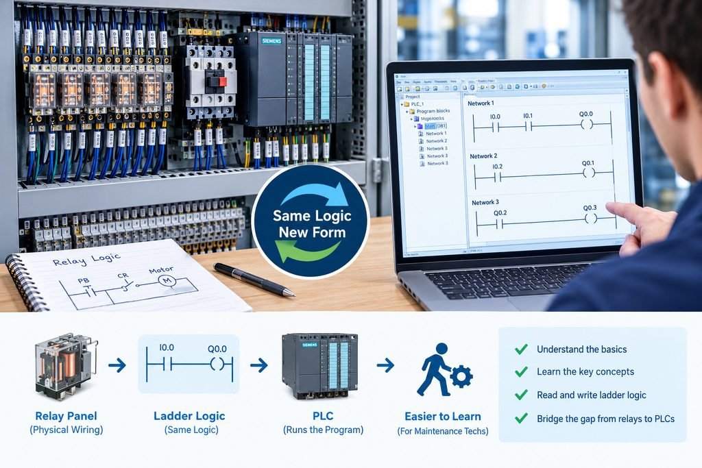
You are standing at an open control cabinet. Inside there is a row of relays, a motor starter, a terminal strip with a number on every wire, and a PLC sitting next to all of it, doing the same job the relays used to do. The junior tech beside you points at the laptop screen and asks the naive question.
“Is that a wiring diagram?”
“No. That is the program.”
“So why does it look like a wiring diagram?”
That question is the whole article. Ladder logic is a programming language that was drawn to look like the relay panels electricians already wired, and that visual trick is the reason a maintenance tech can learn it faster than almost any other language. The drawing is the program. The PLC reads it top to bottom, left to right, over and over, until you stop it.
| QUICK ANSWER Ladder logic is a graphical programming language standardized in IEC 61131-3, the same standard that defines Function Block Diagram, Structured Text and Sequential Function Chart. It mimics a relay control circuit on purpose, so a contact in the drawing does not describe a physical switch. It describes a condition: is this bit a 1 or a 0. |
“Is ladder logic a program or a drawing?”
“Both. It is a drawing that happens to be executable.”
The apprentice frowns at that. “That sounds like a trick answer.”
“It is not a trick, it is the design intent. When the first PLCs replaced relay panels in the late 1960s, the people who had to keep them running were electricians. Nobody was going to hand an electrician a compiler and a text editor. They handed them a screen that looked like the panel they had maintained for twenty years, and the panel logic transferred straight across.”
So the drawing is the program. Two vertical rails: the left rail is the power rail, the right rail is the return. Between them you place contacts, which pass or block the flow, and coils, which do something. Where a relay panel had a live 120 V control wire, ladder has a logical current flowing from left to right along a rung. The PLC evaluates the rungs in order, top to bottom, one after another, and then it does the whole thing again. That complete pass is the scan.
IEC 61131-3 lists five programming languages for programmable controllers: Ladder Diagram, Function Block Diagram, Structured Text, Instruction List and Sequential Function Chart. Section 8 of the article you are reading right now is a small Sequential Function Chart in disguise, because a first project is a sequence.
“But which one should I learn first?”
“Ladder, if you came out of the field. Structured Text if you came out of software. The machine does not care. It runs the compiled result either way.”
There is one piece of vocabulary to lock in before anything else, because it is a trap. In ladder logic, contacts are named after the state of the bit, not the state of the field device. A normally open contact conducts when its bit is 1. A normally closed contact conducts when its bit is 0. That is all. Hold on to that sentence, because nearly every beginner mistake later in this article traces back to forgetting it.
Table 1: The five IEC 61131-3 languages and where each one fits
| Language | Visual style | Typical use |
| Ladder Diagram (LD) | Rungs, contacts, coils | Discrete interlocking, motor control |
| Function Block Diagram (FBD) | Blocks wired together | Process control, analog loops |
| Structured Text (ST) | Text, Pascal-like | Math, recipes, array handling |
| Instruction List (IL) | Text, mnemonic list | Legacy platforms, deprecated |
| Sequential Function Chart (SFC) | Steps and transitions | Machine sequences, batch steps |
The relay panel you already understand
Here is the reassuring part. You already know ladder logic. You learned it before you knew the name.
A classic relay panel has a control transformer that produces a control voltage, usually 24 V DC or 120 V AC. The control voltage goes out to a field device: a push button, a limit switch, a pressure switch. When the device closes, current flows into the coil of a relay. The relay pulls in. A contact on that relay closes, and that contact might energize a motor starter coil, which closes the three-phase contactor that actually turns the motor.
Every part of that chain has a twin in the ladder editor.
The push button becomes an input terminal, and the bit it drives becomes an input bit. The relay coil becomes an output coil or an internal bit. The relay contact becomes a contact instruction examining that bit. The motor starter becomes an output coil that drives a physical output module channel. Even the wire number has a cousin, because a well-written program names its bits so a stranger can follow the flow.
Table 2: Relay panel hardware and the ladder element it becomes
| Relay panel element | Ladder element | What it actually does |
| Push button or limit switch | Input bit (X, I, %I) | Reports field device state to the CPU |
| Control relay coil | Internal bit (M, B, %M) | Stores a logical state inside the CPU |
| Motor starter coil | Output bit (Y, Q, %Q) | Drives a real output module channel |
| Relay contact, N/O | Normally open contact | Conducts when the bit is 1 |
| Relay contact, N/C | Normally closed contact | Conducts when the bit is 0 |
| Wire number | Bit label or symbol name | Documents the intent of the rung |
| FIELD NOTE A beginner once told me the panel was “the truth” and the program was “a copy”. It is the other way around. On a modern machine the program decides everything, and the panel is just the muscle. Learn to read the program and you can debug the machine from a chair. You can browse the control and monitoring hardware that sits between the two roles in our control and monitoring range whenever you want to see how the field side is packaged. |
From a relay panel to one rung
“So how does a wire become a rung?”
“One conductor at a time. The rule is simple: devices in series with each other become contacts in series. Devices in parallel become contacts in parallel.”
Take a written requirement, the kind a maintenance supervisor might hand you on a scrap of paper: “the conveyor runs when the guard is closed AND the start button is pressed.”
Two conditions, both required. That is series.
| GUARD_CLOSED START_PB CONVEYOR—] [————–] [—————( )— |
Now change one word in the requirement: “the conveyor runs when the guard is closed OR the local start button is pressed.” Two conditions, either one enough. That is parallel.
| GUARD_CLOSED—] [——+————————-( )— | CONVEYOR LOCAL_ST |—] [——+ |
Series is AND. Parallel is OR. Combine them and you get the whole combinatorial logic of a machine, drawn with two shapes and no symbols to memorize.
“But real panels have both, right? A bit of both?”
“All the time. Series of parallels, parallels of series. Read the rung left to right and ask yourself at every element: can the current go on from here, or is it blocked. That single question is the entire skill.”
Notice that the coil at the right end is not a switch. It is an assignment. When the rung finally conducts all the way to the right rail, the coil’s bit is set to 1 for this scan. When the rung is broken anywhere, the coil’s bit is set to 0. There is no partial answer and no half-energized coil. A rung is a true-or-false statement evaluated once per scan.
Draw the logic on paper as a sentence first. The words “and”, “or”, “if” and “unless” translate one to one into series, parallel, contacts and inverted contacts. If you cannot write the sentence, you cannot write the rung. Most beginners who get stuck are stuck in English, not in ladder.
Normally open, normally closed and the LED that lies
This section is where the naming trap opens its jaws, so read it twice.
Look at the stop button on a machine. In the field it is very often wired as a normally closed device. The contact inside it is held closed by spring pressure when the button is not pressed, and pressing the button opens it. The reason is fail-safe behavior: if a wire breaks or a terminal loosens, the circuit opens, and an open circuit on a stop circuit stops the machine. A broken wire must never look like “everything is fine”.
Now open the ladder program. The stop button’s contact in the drawing is also drawn as a normally closed contact, the one with the diagonal slash. A beginner sees that and panics.
“Wait. The field device is already normally closed. The drawing is normally closed too. That is a double negative. Shouldn’t the drawing be normally open?”
“No, and this is the point. The ladder contact is not describing the field device. It is describing the input bit.”
Here is the chain. The field device is wired NC, so while the button is not pressed, current flows through it and the input module sees 24 V. That means the input bit is 1. The program wants the motor to run in that condition, so it needs a contact that conducts when the bit is 1. That is a normally open contact in the drawing.
But hold on. Most programs you will read draw the stop as a normally closed contact. Why?
Because the input module is configured, or the program is written, so that the logic is inverted once, deliberately. With a normally closed contact in the drawing examining a bit that is 1 while the button is untouched, the contact does not conduct, and the machine will not start. Something has to flip.
So which is it? It depends on one thing only: the state of the bit when the machine is idle and healthy. Wire the stop NC and configure the input so an energized field device reports a 1. Then a drawing contact that must conduct while the button is untouched is a normally open contact, and pressing the button drives the bit to 0 and breaks the rung. Wire the stop NC and invert the input in the module configuration, so a closed field circuit reports a 0, and now the drawing contact must conduct on a 0, which is a normally closed contact.
“Do it the second way?”
“Many plants do, but you have to know which convention you are in. The dangerous thing is not the choice. It is mixing conventions inside one cabinet. Pick a convention for the whole site, write it on the inside of the door if you must.”
The fail-safe property survives either way, as long as the stop device is wired normally closed. A broken wire in a NC stop loop removes the permissive, and the machine stops. That is exactly what you want. A broken wire must not read as a pressed start button, which is why start buttons are usually wired normally open, so a broken start wire cannot command a start.
Here is the failure to avoid. When you wire a stop button normally open because “normally open is easier to think about”, you have built a machine that will keep running after the stop wire falls off the terminal. Nobody will notice until the incident report. Wire the stop circuit normally closed and verify that the honest way: pull one terminal off and confirm the machine refuses to run.
Then there is the LED.
The little indicator light on the input module tells you what the module sees at its terminals. It does not tell you what the machine is doing, and it does not tell you whether the program is using that bit. An input LED can be lit while a mechanical cam is between positions. An output LED can be lit while the contactor downstream has welded shut or the overload has tripped. The LED is a report from one point in a chain, not a statement of truth about the machine.
You can watch the same state on a local screen or panel display, which is why operations techs like a dedicated HMI they can read without a laptop. A screen shows you the bit. The LED shows you a terminal. Neither shows you the metal.
Table 3: What each indicator actually tells you
| Indicator | Reports | Does not report |
| Input module LED | Voltage present at the module terminal | Whether the field device is healthy |
| Output module LED | CPU is commanding the channel on | Whether the contactor actually closed |
| Program monitor bit | Value the CPU is using right now | Whether the wire matches the bit |
| Panel pilot lamp | What the lamp circuit is wired to | Which rung set it |
| HMI state text | Whatever the program says | Physical position of the machine |
Sealing in a start button
A push button is a momentary device. Press it, it closes. Release it, it opens. If a conveyor ran only while somebody held the start button, no conveyor would ever run.
So how does a momentary press turn into continuous operation? With the oldest and most important pattern in ladder logic: the seal-in, also called the latch.
“Latch? Like a latch on a gate?”
“Latch like a circuit that holds itself. Watch.”
| START_PB STOP_PB RUN_MOTOR +—] [———–+—-]/[————-( )— | | |—| +—] [———–+ RUN_MOTOR |
Read it in order. The start button and the contact labeled RUN_MOTOR are in parallel, so either one can carry current through that part of the rung. The stop button is in series after them, so it can break the path no matter which branch is conducting. The coil on the right is the motor run output.
Press start. The top branch conducts, the rung reaches the coil, and RUN_MOTOR goes to 1. Release start. The top branch opens. But the bottom branch is now examining RUN_MOTOR, and RUN_MOTOR is 1, so the bottom branch conducts and the rung stays true. The coil holds itself on through its own contact. Press stop. The series contact breaks, the coil drops to 0, the seal-in contact opens, and even after you release stop the rung stays dead because both parallel branches are now open.
“Why does it work with no delay? The contact can’t know the coil is on yet.”
“It knows on the next scan. This is the part beginners have to reason through rather than memorize.”
The CPU does not update the physical output the instant it evaluates a coil. It evaluates all the rungs using the input image from the start of the scan, and it writes the accumulated output results out at the end of the scan. Then it reads fresh inputs at the start of the next scan and runs the whole program again. Some platforms keep separate input and output images for exactly this reason.
So the sequence is: press start, scan N evaluates the rung, the input image still shows the button pressed, the coil is written as 1 in the output image, and at the end of scan N the output image is pushed to the module. Scan N+1 begins, the program reads the new output image including RUN_MOTOR = 1, and the seal-in contact is fresh. The button may be released by then, and it does not matter.
The pitfall is what happens when the processor leaves RUN.
| WARNING On plenty of controllers, outputs are forced to zero when the CPU goes to STOP, or on a power cycle, or on a fault. A seal-in built from an output coil is lost in every one of those cases. If the machine must resume, or if the state must survive a mode change, use a retentive internal bit for the seal, or use the platform’s proper latching instruction and understand exactly how that instruction clears. Never assume a seal-in survives a restart just because it survives a momentary button press. |
The other, subtler trap: a seal-in circuit whose stop contact is a normally open contact in the drawing will start the machine and then never stop it, because the rung never breaks. If you build a seal-in and the stop does nothing, do not reach for the wiring. Read the rung and ask what the stop contact does when the button is untouched.
Timers and counters, the two instructions that cover most machines
“You said I only need two more instructions to write most of a machine.”
“I did, and I meant it. Timers and counters.”
A timer instruction does not measure time in the delicate sense. It measures scans, or it counts down using a CPU time base, depending on platform. What matters to you is that it has a preset, an accumulated value, and at least one done bit. The preset is your target, in milliseconds or seconds or ticks. The accumulated value is where the timer has got to. The done bit is the output you use in the rest of the program.
There are three timer flavors worth knowing.
An on-delay timer starts accumulating when its enable input goes true, and its done bit turns on when the accumulated value reaches the preset. It does nothing while the enable is false, and if the enable drops before the preset is reached the accumulated value resets to zero. Use it for start delays: hold the motor off for three seconds after a button press so a second operator can step clear.
An off-delay timer is the mirror image. Its done bit turns on immediately when the enable goes true, and stays on for the preset time after the enable drops. Use it for a cooling fan that keeps running for two minutes after the drive stops.
A retentive timer keeps its accumulated value when the enable drops, and only clears when you specifically reset it. Use it for run-hour logging or for a nuisance condition that accumulates across cycles, for example three separate short overload trips within an hour.
The counter is simpler. An up counter increments its accumulated value on every false-to-true transition of its count input. When the accumulated value reaches the preset, the done bit turns on. You reset the accumulated value with a separate reset instruction or a reset input, and you must do that deliberately, because a counter that is never reset counts to the preset once and then stays there.
Table 4: Timers and counters, parameters and realistic uses
| Instruction | Key parameters | Accumulated value behavior | Realistic use |
| On-delay timer | Preset, enable, done | Counts up while enable is true, resets when enable drops | Delay a motor start by 3 seconds |
| Off-delay timer | Preset, enable, done | Holds after enable drops, then clears | Run a cooling fan 2 minutes after stop |
| Retentive timer | Preset, enable, reset, done | Survives enable dropping, clears only on reset | Accumulate run hours or repeated trips |
| Up counter | Preset, count input, reset, done | Increments on each rising edge, holds until reset | Batch count of 24 parts per carton |
Read the manual for the exact parameter names on your platform. Some call the done bit DN, some call it Q, some call it TT for “timer timing”. The behavior is the same. If you learn the behavior instead of the mnemonic you can move between brands in an afternoon, which is worth a lot on a site with news and updates from several makes of hardware in the same plant.
Where beginners get stuck
Five things trip up nearly every new programmer. All five are avoidable once you know their names.
1. Writing the same output coil twice. If you put RUN_MOTOR as a coil on rung 12 and again on rung 19, only the last one wins. The CPU evaluates rungs in order, so rung 19 overwrites whatever rung 12 decided, every single scan. The symptom is maddening: the output follows rung 19 and behaves as if rung 12 does not exist. The fix is a discipline, not a trick. Each physical output gets exactly one coil in the whole program, and the logic that could turn it on is combined into the branches that feed that one coil. If you truly need to set and clear from different places, use a set/reset pair on an internal bit and drive the output coil from that bit once, at the bottom.
2. Believing the input LED. Covered above, and it earns its place in this list because it burns experienced people too. The LED confirms one module terminal, nothing more. When you diagnose, compare three things: the field device state, the module LED, and the bit value in the program monitor. When they disagree, the disagreement is the fault, and it is usually a wiring or configuration problem sitting between the device and the module.
3. Forgetting that a rung is instant and a machine is not. A rung executes in microseconds. A pneumatic cylinder takes a second to extend. A motor takes two seconds to reach speed. If you write logic that expects the cylinder to be extended on the very next scan, the program will race ahead of the metal every time. That is what timers, position sensors and permissive conditions are for. Never use a rung’s speed as an assumption about the machine’s speed. Wait for the sensor, or wait for the timer, and only then take the next step.
4. Using a one-shot wrong. A one-shot, or rising-edge instruction, fires its output for exactly one scan when its input goes from 0 to 1. Beginners often build a one-shot out of ordinary contacts and get an action that repeats every scan while the condition holds. The symptom is a counter climbing by fifty instead of one, or a message being sent over and over. The fix is to use the platform’s dedicated one-shot instruction rather than hand-rolling one, and to place it so that the edge is detected on the signal you actually care about.
5. Not labeling internal bits. The most expensive mistake on this list, and the least technical. Six months from now, nobody remembers that M412 is the guard bypass permissive. An unlabeled bit is a landmine that somebody, possibly you at 3 a.m., will step on. Name every bit as you create it, add a comment on every rung that does something nonobvious, and leave the spare bits named as spares.
Table 5: Beginner mistakes and the fix
| Symptom you see | Likely cause | The fix |
| Output ignores earlier logic | Same coil written on two rungs | One coil per output, combine branches |
| Machine acts on stale state | Trusting the LED over the bit | Compare device, LED and monitor bit |
| Step advances too early | Rung faster than the mechanism | Add sensor or timer permissive |
| Counter jumps by many | Rewritten one-shot, or no edge | Use the platform one-shot instruction |
| Nobody can maintain it | Unlabeled internal bits | Name bits and comment rungs as you go |
Your first five rungs, in order
Here is the project. It is small, it is realistic, and it holds almost everything you will need for your first year of maintenance programming. Build it in the simulator before you touch a wire.
- Rung 1, start and seal-in. A start push button in parallel with the run output’s own contact, feeding the run coil. This is the pattern from the seal-in section, and it is rung one because everything else depends on it.
- Rung 2, stop. A normally closed contact in series with the run rung, wired so that pressing stop breaks the seal and drops the run coil. It uses the fail-safe convention you settled on for the site, and you should verify it by removing a terminal, not by pressing the button.
- Rung 3, on-delay timer driving a run permit. The timer’s enable is the run output, so the timer starts when the machine starts. Its done bit is used as a run permit downstream, for example to allow a second motor or a clamp to move only after the first has been running long enough.
- Rung 4, counter for a batch. An up counter counts rising edges from a part-present sensor, with a preset of the batch size. Its done bit signals that the batch is complete, and a separate reset rung clears the accumulated value when the operator acknowledges the batch.
- Rung 5, one alarm bit driven by a timer done bit. A second timer with a longer preset, enabled while the machine is running, whose done bit sets an alarm internal bit. This is a “running longer than expected” alarm, and it is the simplest useful diagnostic a machine can have.
| Project: five rungs, in build order. Rung 1: START_PB OR RUN_MOTOR -> coil RUN_MOTOR (seal-in) Rung 2: (series) STOP_NC contact -> rung 1 feed Rung 3: RUN_MOTOR enable -> TON_1 preset 3s -> RUN_PERMIT Rung 4: PART_SENSOR edge -> CTU preset 24 -> BATCH_DONE ACK_PB -> RESET CTU_1 Rung 5: RUN_MOTOR enable -> TON_2 preset 30min -> ALARM_SLOW Notes: one coil per physical output. Name every internal bit.Rung 5 sets an internal bit only. It does not drive an output directly. |
Now the test procedure, and this part is not optional. Before you connect a real load, work through this checklist.
☐ Put the CPU in a mode that disables physical outputs, or leave the output module unwired, so a mistake cannot move a machine.
☐ Force or simulate every input one at a time. Confirm each input bit changes in the program monitor.
☐ Press and release the simulated start. Confirm the run bit seals in and stays on after release.
☐ Verify the stop works before the start. Break the stop condition first, then try to start. The machine must refuse.
☐ Watch one full scan. Step through a start, a stop and a re-start while watching the timer accumulated values and the counter, and confirm every transition happens where you expect it.
☐ Reset the counter deliberately. Confirm the done bit clears and the batch can start again.
☐ Force the alarm timer to expire, or temporarily reduce its preset, and confirm the alarm bit sets and that no output moves because of it.
☐ Only after all of the above, connect the real load and run it at the lowest speed the machine allows.
The first project is deliberately boring. That is the point. A five-rung program you understand completely is worth more than a fifty-rung program you copied, because when the fifty-rung program misbehaves you will have no idea which rung to trust.
| BOTTOM LINE Ladder logic looks like wiring because it was designed to be read by people who wired. Contacts test bits, coils assign bits, series is AND, parallel is OR, and the scan runs top to bottom until the power goes off. Learn the seal-in, learn one timer and one counter, and you can read most of the programs standing between you and a running machine. |
About TZ Tech
TZ Tech supplies industrial automation, electrical, instrumentation and telecommunications components, including rare and discontinued parts other suppliers can’t source. We buy ready-to-ship distributor stock, so prices stay competitive and lead times stay short.
You get the part you ordered, at the price and lead time we quoted. Legacy and discontinued items come with an honest, accurate report on their real condition, so there are no surprises when the box arrives.
Send your inquiry and you hear back within 6 hours. In-stock items ship without delay.
Every component is screened and inspected before it leaves us. Brand-new parts carry a full 1-year warranty.
If a part isn’t right, we make it right, and we stay reachable after the sale.
Have a project or a part you need? Send us the details and we’ll get back to you fast.
Contact us →