
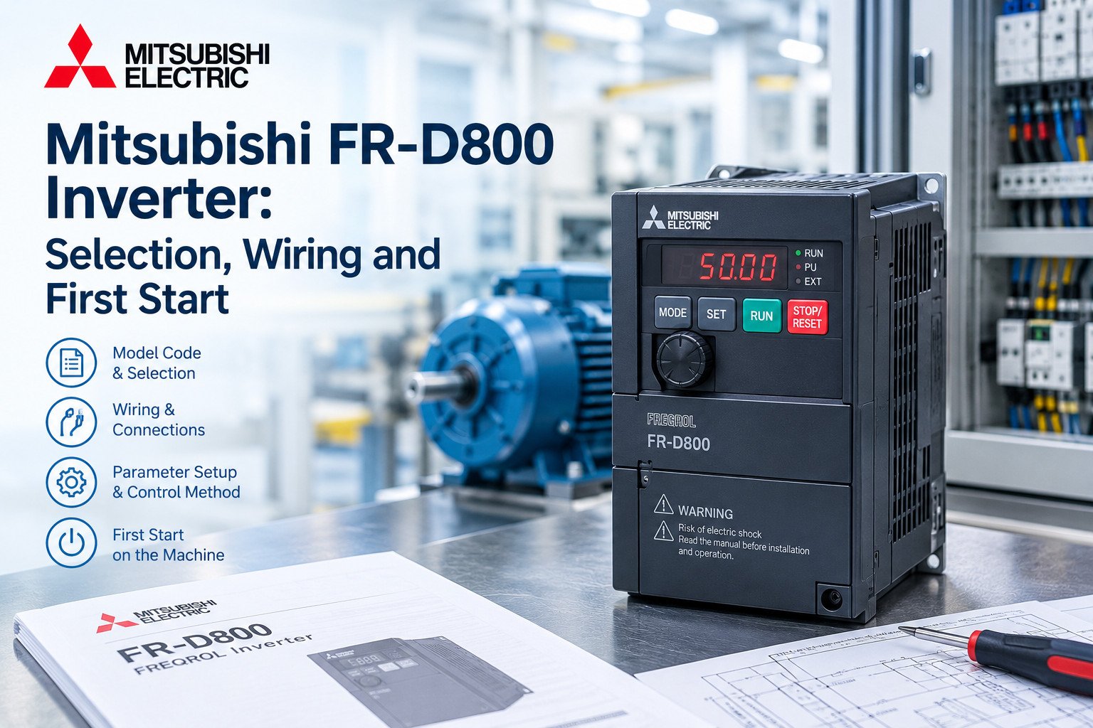
The FR-D800 inverter is the current compact drive in the Mitsubishi Electric FREQROL line. It replaces the FR-D700 and the FR-F700PJ. Four voltage classes run from 0.1 kW to 15 kW. One enclosure covers V/f control, advanced magnetic flux vector control and PM sensorless vector control, so the buying decision is made on the nameplate, not on a feature list.
Most selection errors on this series are model-code errors. The capacity is printed in the part number, the current is printed in the part number, and the duty rating is implied by both. Reading that string before opening a catalog removes most of the guesswork.
Reading the model code before you open a catalog
Take FR-D820-0.4K-025. Every block means something.
FR is the FREQROL prefix. D8 is the series generation, the D800. 20 is the voltage class, three-phase 200 V. 0.4K is the applicable motor capacity in kW at the ND rating, not at the SLD rating and not at whatever the motor nameplate claims. 025 is the inverter rated current at ND, written in units of 0.1 A, so 2.5 A.
Table 1: FR-D820-0.4K-025 model code breakdown
| Block | Meaning | Value in this example |
|---|---|---|
| FR | FREQROL series prefix | FR |
| D8 | Series generation | D800 |
| 20 | Voltage class and phase | Three-phase 200 V |
| 0.4K | Applicable motor capacity at ND | 0.4 kW |
| 025 | Rated output current at ND, 0.1 A units | 2.5 A |
| -60 | Optional suffix, coated circuit board | Not present here |
The voltage class block is where buyers slip. Four classes exist: three-phase 200 V from 0.1K to 15K (FR-D820), three-phase 400 V from 0.4K to 15K (FR-D840), single-phase 200 V from 0.1K to 2.2K (FR-D820S), and single-phase 100 V from 0.1K to 0.75K (FR-D810W). A 400 V drive is not available below 0.4 kW. A single-phase 200 V drive stops at 2.2 kW. Above those points the answer is a three-phase model, and if the plant has no three-phase supply, the answer is a different project.
The -60 suffix appears on models with a coated circuit board. Same ratings, same terminals, different board finish, intended for sulfurous air, dust and condensation-prone enclosures. It does not raise the IP rating. The enclosure is still IP20.
One practical rule: match the last three digits to the motor full-load current at the duty you intend to run, then check that the resulting kW capacity is at or above the motor nameplate. If the two disagree, the current figure wins.
Confirm the exact order number against Mitsubishi’s own catalog page before you place the order, including any suffix. Regional catalogs renumber options, and a missing suffix is a wrong part on a pallet.
ND and SLD: choose the rating, then the capacity
FR-D800 carries two ratings on the same hardware. ND is normal duty. SLD is super light duty. The difference is how hard the output stage is allowed to work, and it changes which frame you buy for a given motor.
SLD lets you select one frame smaller than the motor for light-load duty such as fans and pumps. A fan load has a squared torque curve and rarely demands rated torque at low speed, so the drive can be sized below motor kW and still deliver the application. The trade is transient overload headroom: the trip profile is tighter, and the drive will not tolerate a jammed impeller the way an ND-sized unit will.
Table 2: ND and SLD selection
| Rating | Load character | Frame relative to motor | Typical application | Avoid when |
|---|---|---|---|---|
| ND | Constant torque, full rated torque over the speed range | One frame at or above motor capacity | Conveyors, mixers, extruders, positive displacement pumps | Load can jam or start loaded |
| SLD | Variable torque, torque rises with the square of speed | One frame below motor capacity is permitted | Fans, centrifugal pumps, blowers | High breakaway torque, frequent starts, unknown load |
Field note: Fans and pumps are the only place this writer will sign off on an undersized frame. If the load curve is unknown, if the machine can start against a closed damper or a full pipe, or if the operator can jam it, buy ND and stop arguing about the saving. A tripped drive on a Friday night costs more than the frame difference.
Two more selection points sit outside the ND/SLD choice.
The first is starting torque. V/f control gives a soft start with limited low-speed torque. Advanced magnetic flux vector control improves it on a standard induction motor without an encoder. PM sensorless vector control is the strongest of the three at low speed and requires a permanent magnet motor from the supported list.
The second is the brake. The 0.4K 200 V model has an integrated brake chopper rated for 100% ED. The chopper sinks regenerative energy but the resistor is external and must be sized for the deceleration duty. A drive with a chopper and no resistor is a drive that trips on overvoltage the first time the load overhauls it.
One box, three control methods
The control method is a parameter, not a purchase option. One unit runs V/f, advanced magnetic flux vector and PM sensorless vector, selected through the control mode selection parameter, Pr.800.
Table 3: Control methods available on FR-D800
| Method | Motor feedback | Motor types | Speed holding | Best for |
|---|---|---|---|---|
| V/f control | None | Any induction motor | Load dependent, slips with load | Multi-motor panels, simple fans, retrofits with unknown motors |
| Advanced magnetic flux vector control | None (calculated) | Mitsubishi SF-PR induction motors | Good at moderate speed | Conveyors, pumps and machines needing torque at low speed without an encoder |
| PM sensorless vector control | None (estimated position) | MM-EF/EFS IPM, EM-A global PM, third-party PM with auto-tuning | Best of the three at low speed | High-efficiency PM machines, wide speed range, energy-driven retrofits |
Supported motors are specific and worth writing down before the quote. Mitsubishi induction motor SF-PR for the vector induction mode. Mitsubishi IPM motors MM-EF and MM-EFS. Mitsubishi global PM motor EM-A. Non-Mitsubishi PM motors are supported through auto-tuning, which means the drive measures the motor instead of trusting a datasheet.
Auto-tuning on a third-party PM motor is not a formality. It needs the motor uncoupled or at least unloaded, correct nameplate data entered first, and a stable DC bus. A tuning run on a loaded machine produces a motor model that is wrong in a way that shows up months later as a random overcurrent trip at low speed.
The output frequency range is 0.2 to 590 Hz on the 0.4K 200 V model. Above roughly 60 Hz the motor is in the field-weakening region and torque falls; the drive will happily command 200 Hz into a motor that cannot produce torque there. Frequency range is a drive limit, not a motor capability.
Terminals, inputs and outputs on a compact drive
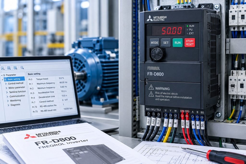
The 0.4K 200 V model carries five digital inputs, one transistor output, one relay output, two analog inputs and one analog output. Control terminals are spring clamp type. The main circuit terminals are screw type. Enclosure is IP20, so the drive belongs inside a panel, not on a wall in a wash-down area.
Table 4: Terminal and I/O summary, 0.4K 200 V model
| Group | Quantity | Notes |
|---|---|---|
| Main circuit input | 3 on three-phase models, 2 on single-phase models | Fuse or breaker ahead of the drive, per the manual |
| Inverter output to motor | 3 | No contactor or switch between drive and motor |
| Protective ground | 1 | Motor frame and panel bonded here |
| Digital input | 5 | Functions assigned by parameter; check common terminal position before wiring |
| Transistor output | 1 | Open collector, suits a PLC input |
| Relay output | 1 | Dry contact for fault or run status |
| Analog input | 2 | Speed reference plus a second setpoint or override |
| Analog output | 1 | Meter or analog input on the PLC |
| RS-485 | 2 | Modbus RTU, daisy chained |
| USB Type-C | 1 | FR Configurator2 connection |
| STO input | 2 | Safety relay contact pair, monitored |
Spring clamp terminals change the wiring method. Solid wire goes in directly. Stranded wire needs a ferrule or a correctly stripped end, and the release tab must be pressed with a tool small enough not to gouge adjacent terminals. Retention is mechanical, so a pull test on each conductor is not optional on a panel that will travel.
Five digital inputs is enough for run, stop, forward, reverse, reset and one external fault, with nothing left over. Any machine needing more than that needs either a parameter remap or a small PLC in front of the drive. Buyers who assume a compact drive has eight inputs end up adding a relay board.
The built-in 4-digit LED display shows the parameter number and the value on the same field, which is the entire HMI. There is no text display. Reading a fault code means knowing the code list, and the manual belongs in the panel door pocket, not in an office drawer.
The brake chopper sits inside the 0.4K 200 V model at 100% ED. External resistor selection follows the deceleration energy, and the resistor must be mounted where its heat can leave the enclosure.
Parameters to set before the first start
Factory defaults are for a bench, not for a machine. Nine settings decide whether the first start is clean.
Table 5: Settings to complete before the first run
| Setting | What it controls | Why it comes first |
|---|---|---|
| Control mode selection (Pr.800) | V/f, advanced magnetic flux vector or PM sensorless vector | Every motor constant downstream depends on this choice |
| Motor capacity | kW value matching the motor nameplate | Reference for tuning and protection |
| Motor rated current | A from the motor nameplate | Reference for the electronic thermal overload |
| Motor rated frequency | Hz from the nameplate | Base point for the V/f pattern and vector model |
| Acceleration time | Ramp from standstill to top speed | Too short trips on overcurrent at start |
| Deceleration time | Ramp from top speed to standstill | Too short trips on overvoltage from regenerated energy |
| Operation command source | Keypad or control terminals | Prevents a drive that ignores the start button |
| Frequency command source | Keypad, analog input or RS-485 | Prevents a drive that runs at the wrong speed |
| STO input assignment | Which safety pair enables the output stage | An unassigned or unjumped STO input means the drive will not run |
Set the motor data before touching the ramp times. A drive tuned against wrong nameplate current will trip on overload at a load that is entirely normal, and the electrician will spend an afternoon on the load instead of the parameter.
Commissioning order, FR-D800

1  Read the model code, confirm voltage class and ND current
2  Compare motor nameplate FLA with drive ND current
3  Enter motor capacity, rated current, rated frequency
4  Select control mode (Pr.800) and run auto-tuning if PM or vector
5  Set acceleration and deceleration times from the mechanical data
6  Select operation command source and frequency command source
7  Assign digital input functions, then test each one
8  Set the electronic thermal overload to motor FLA
9  Verify the STO circuit and confirm the drive reports ready
10 Record every changed parameter on the panel schedule
Step 10 is the one that gets skipped and the one that saves the next person. A drive with forty changed parameters and no record is a drive nobody wants to touch.
Rule of thumb: if the motor nameplate current is within about 10 percent of the drive ND rating, the drive is correctly sized for constant torque. If the nameplate is above the drive rating, go up a frame. Never let the electronic thermal overload be set above motor nameplate current to stop nuisance trips. Fix the ramp or the load instead.
The 4-digit password function restricts parameter read and write. Set it on machines that leave the plant, and write the number into the panel schedule. A locked drive with a lost password is a replaced drive.
USB Type-C, bus power and FR Configurator2
The USB Type-C connector runs FR Configurator2 from a laptop. The useful part is bus power: parameters can be read and written with the main circuit power off, because the USB connection supplies the control board.
The limit matters. USB bus supply is capped at a maximum SCCR of 500 mA, and the PU connector cannot be used while the drive is running on USB bus power. So the workflow is configure, disconnect, then energize. It is not a live-tuning path.
FR Configurator2 adds a trace function and a graph function with high-speed sampling. For commissioning, that turns a nuisance trip into a waveform: you see whether current rose before the trip or voltage rose after the deceleration command, and the fix follows from the shape.
Caution: parameter writes over USB bus power are safe for the drive but not for your record keeping. The laptop sees a drive with no main circuit voltage, so any status or fault history it reads is stale. Copy parameters, save the file with the machine tag in the name, and only then power up.
Parameter files are portable. A known-good set from one machine can be pushed to the next identical machine, which is where the tool pays for itself on a repeat build.
Modbus RTU over the built-in RS-485 port
RS-485 is built in, speaking Modbus RTU, with selectable speeds from 0.3 to 115.2 kbps. No option card, no gateway.
At 115.2 kbps the drive is fast enough for a PLC to poll a handful of registers inside a normal scan. At 0.3 kbps it is fast enough for nothing, and that setting exists for long, noisy runs where the alternative is no communication at all. Most panels land between 9.6 and 38.4 kbps and stay there.
Wiring discipline decides whether the link works. Twisted pair, daisy chain from drive to drive, termination at the two physical ends only, and a common reference conductor between nodes. Star topology on RS-485 produces intermittent faults that look like drive problems.
Set a unique station address per drive before energizing the segment. Two drives at address 1 on the same trunk will both answer, and the PLC will report a checksum error while both machines sit idle.
Speed reference over RS-485 is convenient and slightly dangerous. If the network drops, the drive holds the last command or follows whatever the communication fault action is set to. Decide that behavior at design time, not during a fault.
STO wiring and what it does not cover
STO, Safe Torque Off, is built in. It is driven by an external input signal, typically a dual-channel safety relay contact pair, and it removes the torque-producing voltage from the motor without removing main circuit power.
The function has its own documentation. FR-D800 ships with a separate Functional Safety instruction manual, and that manual, not the general catalog, carries the wiring, the diagnostic coverage and the proof-test interval. Anyone commissioning a safety function on this drive should be holding it.
Warning: STO is not a disconnecting means. It does not isolate the main circuit, it does not de-energize the output terminals, and it does not discharge the DC bus. Lockout and tagout still apply before anyone opens the cover. Treat the output terminals as live until the DC bus indicator is out and the measured voltage is zero.
What STO does cover is the common case: a guard door opens, the safety relay drops both channels, the drive stops producing torque, and the motor coasts or brakes depending on the mechanical setup. Restart requires the safety circuit to be reset and the drive to see a fresh run command. That last part is a design choice, not a default to assume.
Two wiring points cause most of the trouble. Shielded cable for the safety pair, grounded at one end. And a functional check at commissioning: open the guard, confirm the drive reports the safe state, then confirm it will not restart until reset. A safety circuit that has never been tested is a drawing.
Carrying D700 parameters across with the convert function
Existing FR-D700 and FR-F700PJ panels are the reason the convert function exists. FR Configurator2 can take a parameter file from either family and convert it to FR-D800 parameters.
Conversion support for FR-F700PJ files is stated for April 2026. D700 files convert now. That date matters if the project is a rolling retrofit: a batch of mixed panels cannot be converted in one pass until the F700PJ side is supported.
What converts is parameter values. What does not convert is everything physical. Terminal layout differs, terminal count differs, and a digital input function that existed on D700 may need a different assignment on D800. The converted file is a starting point that removes typing, not a validated program.
Run this sequence on the first panel of any retrofit:
- Convert the old parameter file and save it under a new name.
- Compare the converted list against the old list, parameter by parameter, on paper.
- Wire the new drive to the existing drawing and note every terminal that moved.
- Power up with the motor uncoupled and test each digital input and each output.
- Only then couple the load and run the machine through its full cycle.
A converted file gets you to the first start in minutes. The comparison in step 2 is what keeps you from discovering a swapped input function during production.
Pre-start checklist
Print this and keep it with the panel schedule.
- ☐ Model code verified against the motor nameplate current at the intended duty rating
- ☐ ND or SLD rating chosen deliberately, not by habit
- ☐ Voltage class matches the available supply, single-phase or three-phase
- ☐ Exact order number, including any -60 suffix, confirmed against the manufacturer’s catalog page
- ☐ Motor nameplate capacity, current and frequency entered into the drive
- ☐ Control mode selected and auto-tuning completed for a PM or vector setup
- ☐ Acceleration and deceleration times set from the mechanical data, not left at default
- ☐ Operation command source and frequency command source both set to the intended source
- ☐ Each digital input tested individually with the motor uncoupled
- ☐ Electronic thermal overload set to motor nameplate current
- ☐ STO circuit wired with shielded cable and functionally tested, including restart inhibit
- ☐ RS-485 address unique, termination fitted at both ends only
- ☐ Parameter backup saved and the 4-digit password recorded on the panel schedule
- ☐ Brake resistor, if fitted, sized for the deceleration duty and clear of the heat path
Two of these items catch more faults than the rest: the command source settings and the STO circuit. A drive with the wrong command source looks dead with the terminals wired correctly. A drive with an unjumped STO input looks dead with everything correct.
The FR-D800 rewards a buyer who reads the code string and a commissioning tech who writes down what changed. Nothing on this drive is exotic. The failure mode is assumption: assuming the frame is right because the kW matched, assuming the input count is enough, assuming STO isolates. Each of those costs a shift.
About TZ Tech
TZ Tech supplies industrial automation, electrical, instrumentation and telecommunications components, including rare and discontinued parts other suppliers can’t source. We buy ready-to-ship distributor stock, so prices stay competitive and lead times stay short.
You get the part you ordered, at the price and lead time we quoted. Legacy and discontinued items come with an honest, accurate report on their real condition, so there are no surprises when the box arrives.
Send your inquiry and you hear back within 6 hours. In-stock items ship without delay.
Every component is screened and inspected before it leaves us. Brand-new parts carry a full 1-year warranty.
If a part isn’t right, we make it right, and we stay reachable after the sale.
Have a project or a part you need? Send us the details and we’ll get back to you fast.
Contact us →