
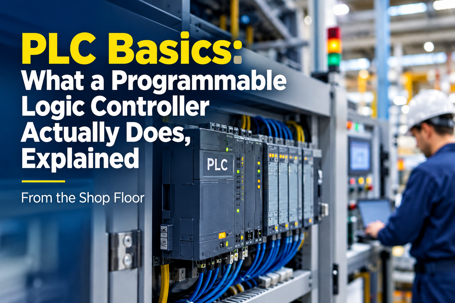
PLC Basics: What a Programmable Logic Controller Actually Does, Explained From the Shop Floor
Twenty-two years on the floor, and the question I still get asked most often comes from the new guy standing at the panel: “So what does this box actually do?”
Fair question. Somebody hands him a manual, the manual opens with scan cycles and data types, and by page four he has quit reading. So here is the answer the way I would give it with a cold coffee sitting on top of the cabinet and a drive fault LED blinking behind us.
A PLC is a small industrial computer that reads switches, thinks about them using a program somebody wrote, and switches things on and off. That is the entire idea. Everything else is detail piled on top of that one sentence: how it reads, how it thinks, how it switches, and what goes wrong when any of those three stops working.
I have replaced enough of these things to know that the beginners who learn fast are the ones who get that sentence straight first. The ones who struggle are usually trying to memorize instruction sets before they understand what the hardware is doing.

What a PLC actually is
Programmable Logic Controller. Older guys still call it a “programmable controller,” and in some plants you will hear it called a “PC” or even a “black box.” Same thing.
The word that matters in that name is *programmable*. Everything before 1968 did the same job with relays. If you wanted to change how a machine behaved, you rewired it. A panel full of contactors, timers, and terminal strips was the logic. Change the sequence, and somebody stood there for two days with a screwdriver and a wiring list.
A PLC replaced the wiring with a program. The field wiring stayed roughly the same, the logic moved into memory, and changing the sequence became a laptop job instead of a wiring job. That is why PLCs took over every factory on earth in about fifteen years. Not because they were faster. Because maintenance could change them without a drawing revision.
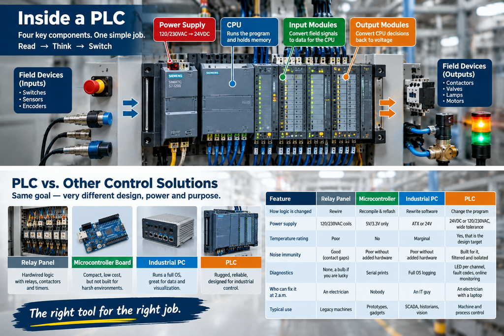
Four things sit inside the box, and every one of them is a failure point I have had to deal with:
- A CPU, which runs the program and holds the memory.
- Input modules, which convert field signals into something the CPU can read.
- Output modules, which convert the CPU’s decisions back into voltage that moves a contactor, a valve, or a lamp.
- A power supply, which usually converts 120V or 230V plant power down to 24VDC for the logic and the field devices.
A fifth thing sits outside the box and gets blamed constantly: the wiring between the two. Roughly two-thirds of the “PLC problems” I get called out to are not PLC problems at all. They are a loose terminal, a failed sensor, a shorted solenoid, or a power supply that has drifted down to 19 volts after eight years in a hot cabinet.
Plastic box, microcontroller board, industrial PC, or PLC?
The confusion here is real, because a modern PLC contains a microcontroller, and some industrial PCs run PLC software. The differences that matter in a plant are not about silicon. They are about power supply range, temperature rating, certification, and how easy the thing is to swap on a Sunday.
| Relay panel | Microcontroller board | Industrial PC | PLC | |
| How logic is changed | Rewire | Recompile and reflash | Rewrite software | Change the program |
| Power supply | 120/230VAC coils | Regulated 5V/3.3V only | ATX or 24V | 24VDC or 120/230VAC, wide tolerance |
| Survives 50°C cabinet | Yes, badly | No | Marginal | Yes, that is the design target |
| Noise immunity | Good (contact gaps) | Poor without added hardware | Poor without added hardware | Built for it, filtered and isolated |
| Diagnostics | None, a bulb if you are lucky | Serial prints | Full OS logging | LED per channel, fault codes, online monitoring |
| Who can fix it at 2 a.m. | An electrician | Nobody | An IT guy | An electrician with a laptop |
| Typical use | Legacy machines | Prototypes, gadgets | SCADA, historians, vision | Machine and process control |
The reason a $300 microcontroller board cannot replace a $900 PLC in a panel is not processing power. It is that a PLC is specified for 24VDC wired the wrong way round, 60°C, vibration, and a plant electrician with a screwdriver. That is what you are paying for, and it is worth the money every time a cabinet door gets left open in August.
If you want to see how the ranges compare across brands, our PLC listings cover both current and discontinued families.
The scan cycle: learn this before anything else
This is the part that separates people who fix problems from people who guess.
A PLC does not watch everything at once. It runs a loop, over and over, thousands of times a second. That loop has stages, they always happen in the same order, and the order explains a whole category of faults that otherwise make no sense.
| Stage | What the CPU does | What it means when something goes wrong |
| 1. Input scan | Copies the state of every input module into the input image table in memory | The CPU sees a snapshot, not live wiring. A pulse shorter than the scan can be missed entirely |
| 2. Program execution | Runs the program from top to bottom, left to right, using the image table | Rung order matters. A rung that reads a coil set later in the program reads last scan’s value |
| 3. Output scan | Copies the output image table out to the output modules | Outputs hold their state through the whole program scan. A coil that gets set and reset in the same scan never turns on |
| 4. Housekeeping | Communications, diagnostics, LED updates, watchdog | Slow comms traffic can stretch the scan and make timing drift |
Read that table twice. Almost every “impossible” bug a beginner hits is in there.
A start pushbutton that gets pressed for 40 milliseconds on a machine with a 60 millisecond scan will be missed. Not sometimes. Every time, until you latch it in hardware or use a high-speed input. The same pulse on a 5 millisecond scan never gets missed. Nothing changed except the time it takes the CPU to go around the loop.
A coil that an operator swears “was on, I saw the light” can be set on rung 12 and reset on rung 40 in the same scan. The CPU executes both, the output image table ends up off, and the lamp never blinks. On the screen it looks like the program ignored you. It did exactly what you told it.
Two numbers you should know for any machine you look after:
- Scan time, typically 1 to 20 milliseconds for a small machine, longer when the program gets big or comms traffic climbs.
- Scan jitter, the variation between one scan and the next. A steady 8 milliseconds is fine for most logic. A scan that bounces between 4 and 60 milliseconds will make timers behave strangely, and it usually means someone added a block, a device, or a scan task that should not be there.
On an S7-300 with a few hundred instructions, 3 to 6 milliseconds is normal. An older SLC 500 running a thousand instructions can sit around 10 to 20 milliseconds. A modern S7-1500 or ControlLogix running the same logic is under a millisecond, which is why people who migrate from legacy hardware are often shocked at how much tighter their timers become. If you are maintaining older Siemens gear and want the family differences laid out, see our Siemens listings and the programming notes for each family.
Inputs: how the PLC hears the plant
Inputs are where the operator’s finger, the photoelectric sensor, the limit switch, and the pressure switch talk to the CPU. Almost all field wiring in a modern panel is 24VDC, with 120VAC and 230VAC still common on older machines in North America.
The first thing to get straight is sinking versus sourcing, because it causes more swapped modules than anything else.
| Input type | Field signal | How it wires | Where you see it |
| Sinking (NPN) input | 24VDC | Sensor pulls the input terminal down to 0V | Asia-built machines, some Japanese OEM panels |
| Sourcing (PNP) input | 24VDC | Sensor pushes 24V into the input terminal | Most European and North American panels |
| Dry contact input | 24VDC, no polarity | A voltage-free contact closes to the common | Pushbuttons, float switches, relay contacts |
| 120VAC input | 120VAC | Line voltage directly to the module | Older North American machines, some safety circuits |
| Analog input | 4-20mA | Two wires, current loop | Pressure, level, flow transmitters |
| Analog input | 0-10V | Two wires plus reference | Potentiometers, older drives, cheap sensors |
| Analog input | RTD or thermocouple | Dedicated module, cold junction compensation | Temperature, ovens, process skids |
Sinking and sourcing confuse people because the words describe the input circuit and the sensor differently depending on which manual you read. Use the practical version. A sourcing sensor sends voltage out to the input. A sinking sensor pulls the input down to ground. If your sensor is PNP and your module expects NPN, the LED on the module will not light. That is the whole symptom. It is not a bad module.
A few things I have learned the hard way around inputs:
- Do not feed the PLC’s sensor supply to everything in the panel. A 24V sensor supply rated at one amp is not for contactor coils, indicator lamps, and a solenoid valve. When it sags, the CPU reads phantom inputs and the machine does odd things. Give each circuit its own fused supply.
- Two-wire 4-20mA loops need the module’s loop supply to be adequate. A loop that reads fine on a bench can drop to 3.6mA at the transmitter with 300 meters of cable. Check the resistance budget before blaming the transmitter.
- Reed switches and proximity sensors fail open more often than they fail short. If a machine stops with an input LED that never lights, meter the sensor, not the module. Nine times in ten it is the sensor.
- Inductive proximity sensors have a leakage current when off. On a short wire that is harmless. On a long run it can hold an input high and look like a stuck signal. A bleeder resistor fixes it, and it is a twenty-minute job versus a two-day investigation.
Outputs: how the PLC moves the plant
Output modules are where the money gets spent, literally. A shorted solenoid takes out an output channel, and a panel full of contactors switching without suppression will take out several over a few years.
| Output type | Switching device | Best for | Watch out for |
| Relay output | Mechanical contact | Mixed AC/DC loads, low cycle rate | Contact wear, 100,000 to a few million operations, slower switching |
| Triac or AC solid state | Semiconductor, AC only | AC solenoids, lamps, high cycle rate | Leakage current even when off, hates inductive kickback |
| Transistor output, DC | Semiconductor, DC only | 24VDC valves, high-speed pulsing | Needs external suppression, no isolation between channels on some models |
| Analog output | 4-20mA or 0-10V | VFD speed reference, proportional valves | Scaling errors, ground loops, unshielded cable |
The single highest-value habit I can hand you is this: put a suppression device on every inductive load. A contactor coil without an RC snubber or a flyback diode will arc across the output contacts every time it drops out. Relay outputs survive it longer. Triac and transistor outputs die from it. On a machine I look after with fourteen contactors in one panel, adding snubbers ended a run of output module failures that had been going on for two years. The snubbers cost less than one of the modules. If you need spares for a legacy panel while you sort that out, our Allen-Bradley listings and Mitsubishi listings cover the older 1771, 1746, and FX families that are still running in a lot of plants.
One more output rule that saves confusion during commissioning: on most modular systems, the output module does not care whether the field device is connected. It will happily report “on” on the LED and in the program while the solenoid sits dead because a fuse blew downstream. Check the field fuse before you suspect the module.
Memory: what the CPU is actually holding
Beginners think of memory as storage. In a PLC it is better to think of memory as addresses, and the program as a list of instructions that read and write those addresses. That is why the same numbers keep showing up on drawings and in manuals as I0.0, Q0.1, M10.5, DB1.DBW0, N7:0, and so on.
The letters vary by brand. The idea does not.
| Address type | What it holds | Typical notation | Notes |
| Digital input | On or off, read from the field | I0.0, X0, %I0.0 | Refreshed once per scan |
| Digital output | On or off, driven to the field | Q0.1, Y5, %Q0.1 | Held until the next output scan |
| Internal bit or marker | On or off, logic only | M10.5, M100, %M10.5 | No physical terminal |
| Timer | Elapsed time and done bit | T4:0, T37, %DB1 | On-time, off-delay, retentive variants |
| Counter | Count value and done bit | C5:0, C1, %C1 | Counts up, down, or both |
| Retentive memory | Survives a power cycle | MB10, B3:0 | Needs battery or EEPROM support on older CPUs |
| Data block or register | Numbers: integers, reals, strings | DB1.DBD4, N7:10, D100 | Word, double word, float sizes |
| System memory | Clock bits, diagnostics, first-scan flags | SM0.0, S:1/15, %S0 | Brand specific, worth knowing |
| Data type | Size | Range | Where you will use it |
| BOOL | 1 bit | 0 or 1 | Every discrete signal |
| BYTE | 8 bits | 0 to 255 | Raw module data, ASCII |
| INT | 16 bits | -32,768 to 32,767 | Counts, small analog values |
| DINT | 32 bits | About -2.1 billion to 2.1 billion | Counters, totals, timestamps |
| REAL | 32 bits | Floating point | Scaling analog inputs, PID, flow math |
| STRING | Variable | Text | Barcode readers, HMI messages, recipe names |
The practical trap sits at the bottom of that table. A REAL that has been copied into an INT gets truncated, and an operator watching a tank level will report that the number “sticks.” Almost every scaling error I have traced has been a data type mismatch, not a math error. If your analog value jumps in steps of 10 or 100 and never lands in between, look at the data types before you touch the scaling formula.
Retention is the other classic. Older CPUs keep the program and retentive values alive on a battery, and a dead battery means the program either comes back from EEPROM or it comes back empty. If a machine powers up with no program after a long weekend outage, the battery is the first thing to meter. Not the CPU. I have replaced CPUs that did not need replacing because nobody checked a $14 battery first.
PLC sizes, and what is still running in real plants
Vendors sort their ranges by I/O count and features. The sorting is useful because it tells you what the machine was built for.
| Class | Typical I/O | Where it lives | Examples you will meet | Notes |
| Nano or brick | 8 to 24 points | Inside a small machine, on the machine frame | Siemens LOGO!, Mitsubishi FX1S, Omron ZEN | Built-in I/O, no rack, no expansion or minimal |
| Micro | 24 to 256 points | Small panels, standalone machines | Siemens S7-200, S7-1200, Allen-Bradley MicroLogix 1100/1400, Micro800, Mitsubishi FX3U, FX5U, Omron CP1H | Most common class for single-machine control |
| Modular | 256 to thousands | Full control panels, racks | Siemens S7-300, S7-1500, Allen-Bradley SLC 500, CompactLogix, Mitsubishi Q and iQ-R, Omron CJ | Card per function, expandable, replaceable channel by channel |
| High-end or redundant | Thousands | Process plants, power stations | Siemens S7-400, S7-1500R, ControlLogix, ABB AC 800M, Honeywell C300 | Redundant CPU, hot swap, long lifecycles |
| PC-based | Depends on the card set | Cabinet-mounted industrial PC | Beckhoff TwinCAT, Siemens WinAC, CODESYS on industrial PCs | Windows or real-time OS, PLC logic in software |
Look at the second row and the third row again, because that is where most of the world’s machines actually sit. A plant with forty machines does not have forty S7-1500s. It has a mix of whatever was installed when each machine was bought: an S7-300 from 2004, an SLC 500 from 1997, an FX2N from 2001, a C200H from the early nineties, and maybe two or three newer machines on newer hardware.
That is also why discontinued hardware still matters. When a plant has thirty machines on one legacy family, the spares shelf keeps production running. It is not sentiment. A $600 obsolete output module on the shelf beats a four-day lead time and a stopped line.
The five programming languages, and which one you should learn first
IEC 61131-3 defines five languages. Every major brand supports them or something close enough to argue about. What actually matters is which one is on the machine you have to fix.
| Language | Looks like | Good at | Reality on the floor |
| Ladder diagram (LD) | Relay contacts and coils | Discrete logic, maintenance troubleshooting | The default in North America. Learn this first |
| Function block diagram (FBD) | Boxes with wires between them | Analog, PID, drive control | Common in European process panels |
| Structured text (ST) | Pascal-like code | Math, loops, data handling, recipes | Growing fast, standard on new machinery |
| Instruction list (IL) | Assembly-like mnemonics | Compact legacy programs | Older Siemens STL, some legacy systems |
| Sequential function chart (SFC) | Steps and transitions | Machine sequences, batch steps | Used for step logic, often mixed with ladder |
For a maintenance tech, ladder is the priority, and it is not close. Ladder was designed to look like the relay drawings electricians already read. A rung with two contacts in series reads exactly like the physical circuit it replaced. If you can read a control drawing, you can read ladder with a two-day head start.
Structured text is the second one to pick up, because new machines arrive with it and the people who can read both get called when the straighter problems are solved. Function blocks come third unless you work in a process plant, in which case move them up.
Something most training courses skip: the fastest way to learn to read ladder is to open a running machine’s program and trace one sequence. Pick a conveyor start circuit. Watch the input LED light, then find the contact with the same address in the program, follow the rung to the output coil, then find that output’s terminal and meter it. One sequence, start to finish, on a real machine, teaches more than a week of simulator exercises.
How to pick a PLC for a job
People ask for recommendations as if a brand is the answer. The brand is the last decision, not the first. Answer these in order and the range picks itself.
| Decision | The question that settles it | Why it matters later |
| I/O count and type | How many digital in, digital out, analog in, analog out, and any special modules? | Headroom on I/O is where expansion lives. Buy 20 percent spare |
| Scan time and speed | Are there high-speed inputs, encoders, or fast pulses? | High-speed counting needs a dedicated module, not faster logic |
| Communications | What does it have to talk to? PROFINET, EtherNet/IP, Modbus TCP, PROFIBUS DP, serial? | Protocol mismatch is the most expensive mistake in this list |
| Existing plant standard | What do the electricians already know and stock? | A brilliant PLC in a brand nobody can program is a liability |
| Lifecycle | Is the family still in production? What is the announced end-of-life date? | Buying into a family two years from phase-out changes the whole cost picture |
| Environment | Cabinet temperature, dust, washdown, corrosive atmosphere, vibration? | Panel temperature above 55°C shortens every electronic life in the cabinet |
| Spares and support | Can I buy a replacement CPU this year, and the year after? | This is what keeps a line running at year eight, not year one |
| Software cost | Is the programming tool licensed, free, or legacy-only? | An unsupported legacy programming package can be harder to source than the hardware |
The order matters. A plant that picks on communications and lifecycle spends less money over ten years than a plant that picks on price and brand familiarity, every single time I have watched it happen.
What actually kills a PLC
The CPU almost never fails. I have seen maybe four genuinely dead CPUs in two decades, and two of those were lightning damage. What fails is everything around it.
| Symptom | Usual cause | First thing to check |
| CPU fault LED, no run | Power supply sagging, backplane fault, program error | Measure 24V at the CPU terminals, not at the supply terminals |
| Random I/O behavior, no pattern | Bad grounding, missing suppression, noisy VFD cable in the same duct | Grounding scheme first, then cable routing |
| Inputs that stay on | Leakage current from a two-wire sensor, shorted field wiring | Disconnect the field wire at the terminal and watch the LED |
| Outputs failing repeatedly on one group | Inductive load without suppression | Add snubber or flyback diode, then replace the module |
| Rack OK, one card dead | Card seated badly, backplane damage, hot swap without support | Reseat and check for bent pins before ordering |
| Program lost after outage | Dead battery, corrupt memory card, EEPROM not up to date | Battery voltage and the memory card write-protect switch |
| Communications dropouts at midday | Cabinet temperature, cable shield drain, switch port negotiated wrong | Panel thermometer, then the cable and the switch |
| Everything fine until a contactor pulls in | Power supply undersized, shared ground with coils | Separate the supply, add filtering |
The theme in that table is that the PLC is usually reporting somebody else’s problem. Learn to read it as a witness rather than a suspect and your diagnostic time drops in half.
What to keep on the shelf
For a plant with any legacy PLC family in service, the shelf list writes itself once you know what fails first. Racks and CPUs rarely die. Power supplies, output cards, and communications modules do.
- Power supplies. First in line, always. A seven-year-old supply drifts, and every phantom input in the plant traces back to it.
- One spare output module per family and voltage class. Outputs take the field abuse, so they fail at several times the rate of inputs.
- One spare input module, shared across machines. Inputs are the next most common failure.
- CPU battery or battery module. Cheap, expires, and takes the program with it.
- Memory card or EEPROM with the current program on it. A spare CPU without the program on it is a spare doorstop. Update the card every time the program changes, and note the revision on the label.
- Communications module for whatever network the plant uses. These tend to be discontinued first and are the hardest parts to source on short notice.
- Terminal blocks, backplane connectors, and one rack segment. The mechanical parts are the ones nobody stocks and everybody needs.
- A printed program listing and the original project file. Digital backups live on servers that get migrated. Paper in the cabinet door survives.
The rule I use: for every legacy family running a critical machine, the shelf should be able to replace the three most failure-prone components without a purchase order. Everything else can wait for delivery. That single rule has saved more production hours for the plants I look after than any upgrade project.
Questions I get asked constantly
What is a PLC, in plain language?
A small industrial computer that reads switches and sensors, runs a logic program, and switches outputs to control a machine or process. It is designed for a control cabinet rather than an office: 24 volt power, wide temperature range, and I/O modules the plant electrician can swap without a laptop full of drivers.
How does a PLC work, step by step?
It runs a loop. First it copies every input’s state into memory. Then it executes your program from top to bottom using that snapshot. Then it writes the output results out to the output modules. Then it handles communications, diagnostics, and internal housekeeping. Then it starts over. That loop is the scan cycle, and it runs thousands of times per second on modern hardware.
Do I need electrical theory before I learn PLCs?
Yes, the basics, and you need them more than you need programming theory. If you understand a relay circuit, a voltage divider, sinking and sourcing, and how to meter a 4-20mA loop, learning the programming is straightforward. If you skip the electrical part, you will be able to write a program that works perfectly on the simulator and blows a fuse in the panel.
What is ladder logic, and is it hard to learn?
Ladder logic is a programming language drawn to look like a relay control drawing, with contacts on the left and coils on the right. For an electrician it is the easiest entry point because the pictures already mean something familiar. Series contacts are AND, parallel contacts are OR, and a coil is the output. The hard part is not the language. It is learning the timing behavior of the scan cycle, and that comes with practice on real equipment.
What is the difference between a PLC, a DCS, and SCADA?
A PLC is a controller built for fast, discrete logic on a machine. A DCS is a controller architecture built for large continuous processes, with everything from the controllers to the engineering tools coming from one vendor. SCADA is software that supervises and visualizes, reading from controllers and drawing the screens operators use. They are not competitors. Most plants run PLCs, DCS, and SCADA in the same building, and a lot of the integration work is making them talk to each other.
How is a PLC different from a relay panel?
The logic lives in memory instead of in wiring. In a relay panel you change the sequence with a screwdriver and a new drawing. In a PLC you change the program on a laptop, and the panel wiring stays as it is. The PLC also adds diagnostics, timers, counters, math, and communications that a relay panel either cannot do or does badly. Relay panels are still used for simple, robust, safety-adjacent circuits, and they will be around for a long time.
What does scan time actually affect?
It sets the resolution of the machine’s awareness. Any event shorter than the scan can be missed. Timers are only as accurate as the scan that drives them. Communications between controllers can lag by a scan or two. If a machine needs to catch a 5 millisecond pulse, you use a high-speed input module or an interrupt, not a faster CPU. Know your scan time before you promise a customer a precise timing specification.
How many I/O points do I need?
Count what the machine has, then add 20 percent spares per I/O type, then check which class that count lands in. The spares are not optional. Every machine gains a sensor during commissioning, a valve during the first year, and an alarm on the second anniversary. Building exactly to the drawing guarantees a rack expansion within eight months.
Which brand should a beginner learn first?
Whichever one is installed where you work, then one more. The concepts transfer between brands almost completely, and the differences are mostly addressing notation and software layout. If you have no machine to work on, Siemens and Allen-Bradley are the two largest installed bases worldwide, and Mitsubishi has a large share in Asia and in imported machinery. Learning two brands makes the third easy.
What software do I need?
Every brand has its own tool, and the licensing model matters as much as the software. Siemens uses TIA Portal for S7-1200, S7-1500, and most modern hardware, with the older STEP 7 and STEP 7 Micro/WIN for S7-300, S7-400, and S7-200. Rockwell uses Studio 5000 for ControlLogix and CompactLogix, and RSLogix 500 for the SLC 500 and MicroLogix families. Mitsubishi uses GX Works2 and GX Works3. Legacy packages are the tricky ones: they need older Windows versions, and finding a licensed copy can be harder than finding the hardware. If you maintain a legacy family, keep a working programming laptop with the right software version on it, and image the hard drive before it dies.
How do I know if a PLC is bad?
Assume it is fine until you have checked everything else. Verify the 24 volt supply at the CPU, not at the supply terminals. Check that the program matches the machine and that the memory card is present. Reseat the module and check the backplane pins. Look for a fault code or a diagnostics buffer entry, which usually tells you the story in one line. When you do replace a CPU, put the original on the bench and test it before you throw it away. I have returned more “dead” CPUs to service than I have buried, and a spare CPU on the shelf is worth real money on a Sunday.
Can I still get parts for older PLCs?
In most cases yes, but the supply has moved from the manufacturer to the aftermarket. Distributors and specialists hold stock of discontinued modules, and that is often the fastest route for a machine that cannot wait six weeks. Check the lifecycle status first so you know what you are buying into, then confirm the firmware or revision compatibility of any replacement before you install it. A module with the right part number and the wrong revision will cause a startup fault that costs a shift to diagnose.
What is a safety PLC, and do I need one?
A safety PLC is a controller certified to a functional safety standard, meaning it has redundancy, self-diagnostics, and a development process that fits the standard for the safety integrity level the machine requires. You need one when the risk assessment says the safety functions must be implemented in the controller rather than in hardware, or when a standards requirement, a customer specification, or a corporate policy says so. For a start circuit on a conveyor, a certified safety relay is often cheaper and simpler. Do not assume a standard PLC can carry a safety function because it has a nice processor.
How do I practice without a machine?
Buy one obsolete brick PLC and a handful of switches, lamps, and a 24 volt supply. It will cost less than a training course and teach you more. Wire a start-stop circuit, then add a timer, then a counter, then an analog input. Read the diagnostics buffer when you deliberately break something. Real hardware, even a thirteen-year-old unit from a surplus shelf, teaches timing, wiring, and noise in a way software simulation never will.
🏢 About TZ Tech
TZ Tech is a leading supplier of industrial automation, electrical, instrumentation, and telecommunications components. We specialize in sourcing ready-to-ship distributor stock, allowing us to offer highly competitive pricing and short lead times. Thanks to our extensive inventory, we can even source rare and discontinued parts that are hard to find elsewhere.
🛡️ Our Quality Commitment
We understand that quality is your top priority. Every component undergoes a strict screening and inspection process so you can buy with absolute confidence. For legacy or discontinued parts, we believe in complete transparency and will always provide an honest, accurate report on the product’s condition. Plus, all brand-new parts come backed by a full 1-year warranty.
Have a project or a part you need? Send us your inquiry today! Our team is dedicated to providing a fast response within 6 hours (excluding weekends).