
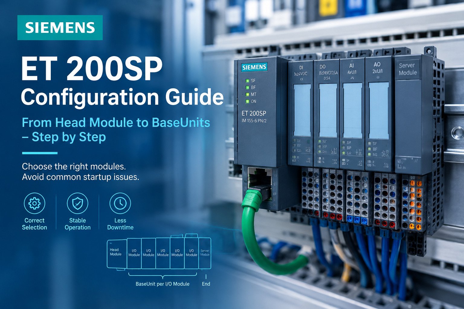
A SIMATIC ET 200SP station is not ordered as a single part number. You order a head module, a set of I/O modules, a BaseUnit for each of those I/O modules, and a server module that closes the rail. Two of those decisions look cosmetic. They decide whether the station starts.
Most commissioning delays on this platform come from the BaseUnit, not from the field wiring. The I/O module is usually right. The 24 V supply is usually right. The station still refuses to start because a light BaseUnit opened a potential group that nobody fed.
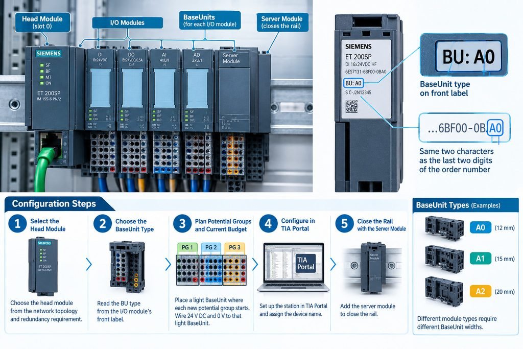
The fix is to select in a fixed order: head module first, BaseUnit type second, potential groups and current budget third, TIA Portal configuration and device name last. Work that way and the parameter assignment error on the DIAG LED becomes something you catch on a drawing instead of something you chase with a multimeter at 2 a.m.
Quick answer: read the BU type off the I/O module’s front label, buy exactly that type in the width the module needs, place a light BaseUnit where each new potential group starts, wire 24 V DC and 0 V to that light BaseUnit, then close the rail with the server module.
What the head module is, and where it sits
The head module occupies slot 0 and starts the backplane bus. Everything to its right inherits communication and, where the BaseUnit type allows it, the 24 V DC supply carried through the backplane.
On a PROFINET station the head module is an interface module. On a station that needs its own logic, an ET 200SP CPU can act as the head instead. The CPU 1510SP F-1 PN (6ES7510-1SJ01-0AB0) is one example. Put that on slot 0 and the rail becomes a small controller with distributed I/O on the same piece of DIN rail.
The distinction matters for panel builders because it changes the panel footprint and the network design. A station with an interface module is a remote I/O island that answers to a higher-level controller. A station with an ET 200SP CPU is an autonomous unit that happens to use the same I/O modules and the same BaseUnit family.
Either way, the head module has one slot for a BusAdapter. The BusAdapter carries the physical PROFINET connection, for example a 2xRJ45 adapter or a fiber variant. Choose the adapter from the cable and the topology you have, never from the I/O count.
Which interface module to order
Siemens groups the PROFINET interface modules into three classes that are abbreviated in the type name.
Table 1: Interface module classes in the ET 200SP type name
| Class code | Full name | How to read it |
|---|---|---|
| BA | basic | Fewest functions, lowest cost. Fits plain I/O islands with no redundancy demand. |
| ST | standard | Middle of the range. Fits most machine-level stations. |
| HF | high feature | Most functions, redundancy, isochronous mode, more modules. |
The class code is not the whole story. Inside the HF class, the numbered variants differ enough that the order number is what you actually put on the purchase requisition.
Table 2: ET 200SP PROFINET interface modules commonly quoted by order number
| Interface module | Order number | Distinguishing property | Where it fits |
|---|---|---|---|
| IM 155-6 PN/2 HF | 6ES7155-6AU01-0CN0 | Two ports, up to 64 I/O modules plus 16 ET 200AL modules, S2 system redundancy, multi-hot swap, 0.25 ms, isochronous mode | General-purpose PROFINET station, including redundant ones |
| IM 155-6 PN/3 HF | 6ES7155-6AU30-0CN0 | Three-port high-feature variant | Line or ring topology without an external switch |
| IM 155-6 PN R1 | 6ES7155-6AU00-0HM0 | R1 variant, supports I/O modules with value status | Stations that consume value status from the I/O modules |
| IM 155-6 PN HA | 6DL1155-6AU00-0PM0 | High Availability interface module | Process automation with availability requirements |
A couple of details in that table earn their place. The IM 155-6 PN/2 HF ships with the server module, so a station built on it does not need a separate right-end cover on the first order. The IM 155-6 PN/3 HF pays for its third port by letting you build a line or ring without bolting an external switch into the enclosure, which is often the cheaper and cleaner answer once you count the switch, its power supply, its rail space and its own commissioning.
For plants already running PROFIBUS DP, the IM 155-6 DP HF keeps the station on the existing network. That is a legitimate choice when the segment is proven and the load is stable.
The head module does not decide how many BaseUnit types you need. It only decides how many I/O modules you can hang on the rail and what the station can do at the network level. The BaseUnit plan is a separate drawing.
Pick the head module from the network topology and the redundancy requirement, then pick the BaseUnits from the modules. Never let a BaseUnit shortage push you into a different interface module.
Reading the BaseUnit type off the module
Every I/O module states the BaseUnit type or types it will accept. The information is printed on the front label as BU: A0, or as BU: A0, A1 when two types both fit. The same two characters are the last two digits of the I/O module’s article number.
Table 3: How the BU code shows up in the order number
| I/O module | Order number | Last two digits | Required BaseUnit type |
|---|---|---|---|
| DQ 16x24VDC/0.5A ST | 6ES7132-6BH01-0BA0 | 0BA0 | BU: A0 |
Read that table once and the whole ordering process simplifies. You do not need a lookup tool to know which carrier a digital output module wants. You read the label, or you read the tail of the order number, and you have the answer.
Width is the second decision. BaseUnits come in 15 mm and 20 mm widths. The 15 mm BaseUnit, written BU15, carries standard I/O modules. The 20 mm form, BU20, appears under relay output modules and some technology modules, where the extra width pays for larger components.
Then comes the type code itself, which is where most of the real engineering sits.
Table 4: BaseUnit type codes and the modules they carry
| BU type | Typical modules | What it adds |
|---|---|---|
| A0 | Standard DI, DQ, AI and AQ modules, plus F-DI and F-DQ | 24 V DC carried through the backplane |
| A1 | Same as A0, plus modules that need the extra terminal | Everything from A0 plus an additional function, required for 4-wire transmitters and for thermocouples using the module’s internal reference junction |
| B0 and B1 | Relay output modules, AC input modules, loads needing their own supply | Potential separation. B1 brings its own power terminals and can sit directly right of the interface module. B0 cannot. |
| C0 and C1 | AS-i master and AS-i safety modules | AS-i specific terminal assignment |
| D0 | 20 mm modules such as the AI Energy Meter 480 V AC (6ES7134-6PA20-0BD0) | Modules that do not use the backplane 24 V bus |
Field note: A0 and A1 BaseUnits look identical on the rail. Nothing on the molded plastic tells them apart. Only the order number separates them, so a mixed bin of A0 and A1 in the panel shop is a genuine installation hazard. Label the bags before they go on the shelf.
The B1 detail is worth internalizing for panel layout. A B1 BaseUnit can sit directly to the right of the interface module because it supplies itself. A B0 BaseUnit cannot take that position. If your layout drawing shows a relay module in slot 1 and you specified B0, the drawing is wrong before anyone has cut a wire.
The D0 case is a useful reminder that not every module participates in the backplane supply. The AI Energy Meter 480 V AC measures a separate circuit and does not draw its logic supply from the backplane bus, so its BaseUnit type reflects that independence.
Light and dark BaseUnits, and the potential group
BaseUnits with the same type code still come in two variants, and the difference is electrical rather than mechanical.
Table 5: Light versus dark BaseUnit behavior
| Property | Light BaseUnit | Dark BaseUnit |
|---|---|---|
| Article number pattern | ends 0D (for example 6ES7193-6BP00-0DA0) | ends 0B (for example 6ES7193-6BP00-0BA0) |
| Potential group | Opens a new one | Continues the group of the BaseUnit to its left |
| 24 V DC feed | Must be wired at its A0 and A1 terminals | No feed needed |
| Position on the rail | First BaseUnit of every potential group | Every BaseUnit inside the group |
A potential group is a block of modules that share one 24 V DC feed through the backplane. The light BaseUnit starts that block and accepts the incoming supply. Every dark BaseUnit to its right rides on the same supply without any additional landing.
This gives you a clean way to build stations. Group the modules that share a supply, put one light BaseUnit at the head of each group, and use dark BaseUnits for the rest.
The practical order numbers follow the type and the width.
Table 6: Verified BaseUnit order numbers
| Description | Order number |
|---|---|
| BU15-P16+A0+2D, light | 6ES7193-6BP00-0DA0 |
| BU15-P16+A0+2B, dark | 6ES7193-6BP00-0BA0 |
| BU15-P16+A10+2D+AUX, light | 6ES7193-6BP20-0DA0 |
| BU15-P16+A10+2B+AUX, dark | 6ES7193-6BP20-0BA0 |
| BU15 A1, light | 6ES7193-6BP00-0DA1 |
| BU15 A1, dark | 6ES7193-6BP00-0BA1 |
| BU15 A1 with TC+PT, light | 6ES7193-6BP40-0DA1 |
| BU15 A1 with TC+PT, dark | 6ES7193-6BP40-0BA1 |
| BU20 type B0 | 6ES7193-6BP20-0BB0 |
| BU20 type B1 | 6ES7193-6BP20-0BB1 |
| BU20 type C0 | 6ES7193-6BP20-0DC0 |
| BU20 type D0 | 6ES7193-6BP00-0BD0 |
| Server module | 6ES7193-6PA00-0AA0 |
The server module is the right-end cover. It closes the backplane at the end of the rail, and it is the one item people forget to order because it does not appear in the I/O list of a typical TIA Portal device view until you look for it. Its order number is simple to remember by position rather than by number: it is the part that makes the rail electrically finished.
The 10 A budget inside one potential group
Current carried through the backplane is not unlimited. One potential group can carry a maximum of 10 A.
That number sounds generous until you count module supply currents and the field loads that a group feeds. Add the backplane current of every module in the group, add the sensor supply current drawn from the group’s auxiliary terminals, and compare the total against 10 A.
Table 7: A worked potential group budget
| Line item | Typical contribution | Running total |
|---|---|---|
| Head module backplane draw | small | small |
| Six digital input modules, backplane side | modest per module | rising |
| Auxiliary 24 V sensor feed taken from the group | set by the field devices | the variable that usually decides it |
| Six digital output modules, backplane side | modest per module | check against the limit |
| Decision point | Split into a second potential group with its own light BaseUnit if the total approaches 10 A | New group starts a new budget |
The engineering move is the same every time. When a group gets close to the limit, you do not increase a fuse and hope. You place another light BaseUnit, wire its A0 and A1 terminals, and start a second group. The second group gets a fresh 10 A budget and the first group’s load stops growing.
On real panels this usually means the output side of a station gets its own group. Output modules drive loads, and load current varies with field conditions in a way that input current does not. Separating outputs from inputs into different potential groups also makes troubleshooting simpler, because you can isolate one group without taking the other offline.
Warning: a light BaseUnit with nothing landed on its A0 and A1 terminals opens an unpowered potential group. Every module to its right loses its 24 V backplane supply, and the head module aborts parameterization. The symptom is a flashing red DIAG LED on the module, a flashing SF LED on the interface module, and a parameter assignment error in the diagnostic buffer. Match the light and dark sequence to the potential group plan, and feed every light BaseUnit that opens a group.
How the mismatch shows up in diagnostics
That symptom deserves a section of its own because the fault looks like a configuration problem and is really a wiring problem.
Picture a station where slot 1 holds a dark BaseUnit and slot 2 holds a light BaseUnit with nothing wired to its feed-in terminals. The dark BaseUnit in slot 1 continues the group established by the head module, which is fine. The light BaseUnit in slot 2 does what a light BaseUnit always does. It opens a second potential group.
That second group has no supply. The modules to the right of slot 2 therefore have no 24 V DC over the backplane. The head module cannot parameterize them, so it stops the startup sequence.
What you see in the field:
- A flashing red DIAG LED on the affected module.
- A flashing SF LED on the interface module.
- A parameter assignment error in the station diagnostic buffer.
What you do about it, in order:
- Confirm the BaseUnit sequence on the rail against the potential group drawing, slot by slot.
- Identify every light BaseUnit that has modules to its right.
- Land 24 V DC on terminal A0 and 0 V on terminal A1 of each of those light BaseUnits.
- Restart the station and read the diagnostic buffer again.
The lesson generalizes. A parameter assignment error on an ET 200SP module is a message about the station’s ability to configure the module, and the BaseUnit sequence is one of the first things that can block it. Before you edit the TIA Portal configuration, walk the rail and read the light and dark pattern.
Push-in or screw terminals
Every BaseUnit type exists in more than one terminal style, and the style does not change the BU type code. You can order the same A0 light BaseUnit with push-in or screw terminals.
Push-in is the default for most new panels because it is faster and the connection is repeatable. The spring terminals accept conductors from 0.25 to 1.5 mm² with ferrules. Opening a terminal takes a 3.5 mm blade screwdriver, which is the insertion tool for this platform and worth carrying in the commissioning bag.
Screw terminals are still the right answer where the site standard says so, where the panel is maintained by a crew that prefers them, or where local practice requires a specific termination method. The BU type does not change. You order the same type code with the terminal style the site expects.
Keep that separation in your head when you build the order. The type and width follow the engineering. The terminal style follows the panel shop.
Commissioning sequence for a new station
The order below works whether you are building a station from a parts list or verifying one somebody else built.
- Read the head module requirement from the network. Confirm PROFINET or PROFIBUS DP, the port count, and whether the station needs redundancy. Choose the interface module, or an ET 200SP CPU if the station runs its own logic.
- Choose the BusAdapter from the cable and the topology. Copper or fiber, and the connector count the topology needs.
- List the I/O modules and read the BU type off each one. Note the width and the BU type from the module label or from the last two digits of the order number.
- Sort the modules into potential groups. Keep the total backplane and auxiliary current of each group under 10 A.
- Decide where each light BaseUnit goes. One light BaseUnit at the start of every potential group, dark BaseUnits for everything inside a group.
- Select push-in or screw-terminal versions of the same BU type, following the panel standard.
- Add the server module so the rail is closed and the backplane is terminated.
- Build the station slot map in TIA Portal and assign the device name.
- Power up with the pre-power-up check below completed, then read the diagnostic buffer before connecting any field wiring.
Bottom line: the BaseUnit is the part that carries the engineering. Get the type, the width and the light or dark sequence right, and the rest of the commissioning follows the drawing.
Pre-power-up checklist for the rail
Run this before the supply goes on. It takes ten minutes and it prevents the most common startup failure on the platform.
- ☐ Head module is in slot 0 and seated on the rail.
- ☐ Server module is fitted at the right end and closes the rail.
- ☐ Every I/O module carries the BU type printed on its own front label.
- ☐ Every 20 mm module sits on a BU20 BaseUnit of the correct type code.
- ☐ Each potential group starts with exactly one light BaseUnit.
- ☐ 24 V DC is landed on terminal A0 of every light BaseUnit that opens a group.
- ☐ 0 V is landed on terminal A1 of the same light BaseUnits.
- ☐ No light BaseUnit has modules to its right without a feed.
- ☐ Calculated current per potential group is inside the 10 A limit.
- ☐ Field conductors are within 0.25 to 1.5 mm² with ferrules fitted.
- ☐ BusAdapter is fitted to the interface module and matches the cable.
- ☐ Station slot map and device name are configured in the engineering tool.
The TIA Portal side, and the order it happens in
Configuration follows the hardware, not the other way around. Set the station up in the project the way it is built on the rail, then assign the device name.
TIA Portal menu path
  Project tree > Devices & networks > Add new device > ET 200SP station
  Device view > slot 0: interface module (set the order number)
  Device view > slots 1..n: I/O modules in rail order
  Device view > last slot: server module
  Online access > Assign device name > pick the PROFINET interface > Assign name
  Online & diagnostics > Diagnostics > Diagnostic buffer (read the first entry)
The device view order has to match the physical rail order. A mismatch here produces a parameter assignment error of its own, and it is easy to confuse with the BaseUnit fault described above. Check both.
Station slot map (example)
  Slot 0 : IM 155-6 PN/2 HF      6ES7155-6AU01-0CN0   + BusAdapter 2xRJ45
  Slot 1 : DI 16x24VDC ST        6ES7131-6BH01-0BA0   BaseUnit dark,  BU A0
  Slot 2 : DQ 16x24VDC/0.5A ST   6ES7132-6BH01-0BA0   BaseUnit dark,  BU A0
  Slot 3 : AI 4xU/I 2-wire ST    6ES7134-6HD00-0BA1   BaseUnit light, BU A1  -> feed A0 = 24 V, A1 = 0 V
  Slot 4 : DQ 8xRelay ST         6ES7132-6HF00-0AA0   BaseUnit dark,  BU B0  (check the label)
  End    : Server module         6ES7193-6PA00-0AA0
Terminal designations on the light BaseUnit are worth writing on the panel drawing in full.
Light BaseUnit feed-in terminals
  A0  ->  +24 V DC  (from the group supply)
  A1  ->  0 V       (same supply reference)
  AUX terminals -> available for sensor or load supply from the same group
  Maximum current through one potential group: 10 A
Where the sensors and transmitters change the BaseUnit choice
Power is only half of the BaseUnit choice. The other half is what the module is asked to read.
A 4-wire transmitter needs the A1 BaseUnit. So does a thermocouple that uses the module’s internal reference junction for cold junction compensation. If your instrument list contains either of those, the analog module in question sits on A1, and the A1 order number has to appear in the bill of materials.
This is where a station can be electrically sound and still not work. An A0 BaseUnit under an analog input module that a 4-wire transmitter depends on will not give you the reading you expect. The module powers up, the diagnostics are clean, and the value is wrong.
Cross-check the instrument list against the BaseUnit list before the panel is wired. For how field devices and their supply references are wired into a modern panel, the reference on sinking and sourcing digital inputs and outputs is a useful companion, and sensors and transmitters themselves sit under sensors and probes.
When an ET 200SP CPU is the head instead
Nothing about the BaseUnit logic changes when an ET 200SP CPU takes slot 0. The CPU starts the backplane bus in exactly the same way, the BU types are the same, the potential groups behave the same, and the 10 A limit still applies.
What changes is the project. The station is now a controller, so the engineering tool treats it as one, and the device name assignment process differs from a plain I/O island. Plan the CPU selection the same way you plan an interface module selection: from the network, the program requirements and the redundancy demand, not from the I/O count. Controllers in the same family are listed under CPU and control boards, and the wider control and monitoring category covers the surrounding hardware.
The payoff of putting a CPU on the rail is a smaller panel and one fewer network partner. The cost is that the station now needs its own program, its own backup and its own failure mode. Decide that on the system architecture, not on the price of the head module.
An adjacent option worth knowing about
Siemens also offers the ET 200BL line, a more compact relative in the same distributed I/O family. Its interface module is the IM 155-8 PN, order number 6ES7155-8AR00-0AN0, and the equipment manual for it is dated 08/2026.
Treat ET 200BL as an adjacent option for space-constrained panels rather than as a replacement for ET 200SP. The two lines coexist, and the question of which one a project uses is an enclosure and channel-count question, not a base unit compatibility question. If you are starting a new station today, check the current ET 200BL documentation on Siemens Industry Online Support for its own module and BaseUnit rules before you design it in.
For more articles on station planning, panel hardware and commissioning practice, the news section collects them in one place.
The selection sequence in one paragraph
Read the head module requirement from the network and the program, then choose the interface module or the ET 200SP CPU. Read the BU type off each I/O module’s front label and note the required width. Group the modules so no potential group exceeds 10 A. Put a light BaseUnit at the head of every group and dark BaseUnits inside it. Wire 24 V DC to A0 and 0 V to A1 on every light BaseUnit that feeds modules to its right. Close the rail with the server module. Build the same layout in the engineering tool, assign the device name, and read the diagnostic buffer before you land a single field conductor.
Do that and the parameter assignment error stops being a mystery. It becomes a line on your checklist that was already ticked.
About TZ Tech
TZ Tech supplies industrial automation, electrical, instrumentation and telecommunications components, including rare and discontinued parts other suppliers can’t source. We buy ready-to-ship distributor stock, so prices stay competitive and lead times stay short.
You get the part you ordered, at the price and lead time we quoted. Legacy and discontinued items come with an honest, accurate report on their real condition, so there are no surprises when the box arrives.
Send your inquiry and you hear back within 6 hours. In-stock items ship without delay.
Every component is screened and inspected before it leaves us. Brand-new parts carry a full 1-year warranty.
If a part isn’t right, we make it right, and we stay reachable after the sale.
Have a project or a part you need? Send us the details and we’ll get back to you fast.
Contact us →